Operating Manual WLVCM-BA-10
EN
6 Electrical Installation
6.1 Device Overview
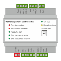
Besides the function-relevant electrical interfaces W1 to W7 (see also chapter 6.2.1), the WLVCM also
has an optical interface O1 which consists of eight LEDs and displays the current system status on the
front of the WLVCM for the user (see also chapter 6.2.2). Figure 2 gives you an overview of these
interfaces.
Figure 3 – Overview of the WLVCM interfaces
6.2 Interfaces
6.2.1 Electrical Interfaces
The below table 1 gives you an overview of the WLVCM electrical interfaces. Chapters 6.2.1.1 to 6.2.1.7
provide details on the individual interfaces and their function.
Electrical interface Function / Description
W1 Supply voltage
W2 Component connection (valve and hotplate)
W3 Digital outlets „status“
W4 Digital inlets „superordinate control“
W5 Temperature sensor
W6 Digital inlet „program start“
W7 USB „communication“
Table 1 – Electrical interfaces W1 to W7 and their relevance