6 Electrical Installation
Operating Manual WLVCM-BA-10
for electrical connection:
• Only use shielded cables for connecting the valve technology!
• In general, signal cables will be laid separately from the energy cables!
• Make sure that lines are always laid straight, never in a ring!
• The environment is very important for the signal transfer. Frequency converters
or other users can significantly influence the signal transfer!
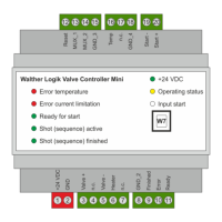
6.2.1.1 Interface W1 „Supply Voltage“
A 24 V voltage source is required for operating the WLVCM and its electronics. It will be connected to
the clamps +24 V and 0 V at the electrical interface „W1“.
Common reference potential for the WLVCM
Table 2 – Overview of the clamps at the electrical interface W1
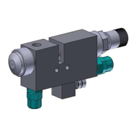
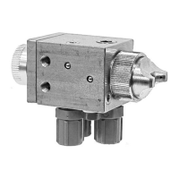
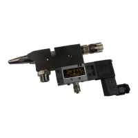
6.2.1.2 Interface W2 „Component Connection“
Table 3 gives you an overview of the clamps at the electrical interface W2 “component connection“.
Depending on their individual documentation, the electro-pneumatic valves will be connected to the
clamps „Valve +“ or „Valve –“ (see also figure 3).
Also, you can control additional hotplates with the WLVCM; they can be mounted at the valve body.
Make sure to connect the contacts of the heating element as shown in figure 3 in order to achieve a
smooth and proper operation. Use the “Heater” clamp as positive connecting clamp for the heating
element. The negative contact of the heating element can be connected to a random clamp “GND_x“
(e.g. clamp “GND“ to Pin2 or „GND_2“ to Pin 8).
Connecting clamp electro-pneumatic valve
Connecting clamp electro-pneumatic valve
Connecting clamp heating element
Table 3 – Overview of the clamps at the electrical interface W2
Figure 4 – Connection of an electro-pneumatic spray, dosing or pulse valve including hotplate
to the WLVCM