Assembly Instructions - Micro Point Pulse Valve MPP-03-PRO
Walther Systemtechnik GmbH – D 76726 Germersheim
Telefon: +49 (0)7274-7022-0 Telefax: +49 (0)7274-7022-91
http://www.walther-2000.de – info@walther-2000.de
4.2 Type Label of Incomplete Device
The type designation is etched in close to the material connection.
The serial number is also inscribed in this area.
5 Start of Operation
5.1 Mounting and Installation
The valves can be installed in any position. The distance to the surface to be applied with the medium
depends on the spray pattern.
Vibrations of the valve caused by fast intermitting cycles require solid and tight installation. The device body
comes with two borings of 5mm diameter which were provided for a solid installation. Machine vibrations to
the valves should be avoided.
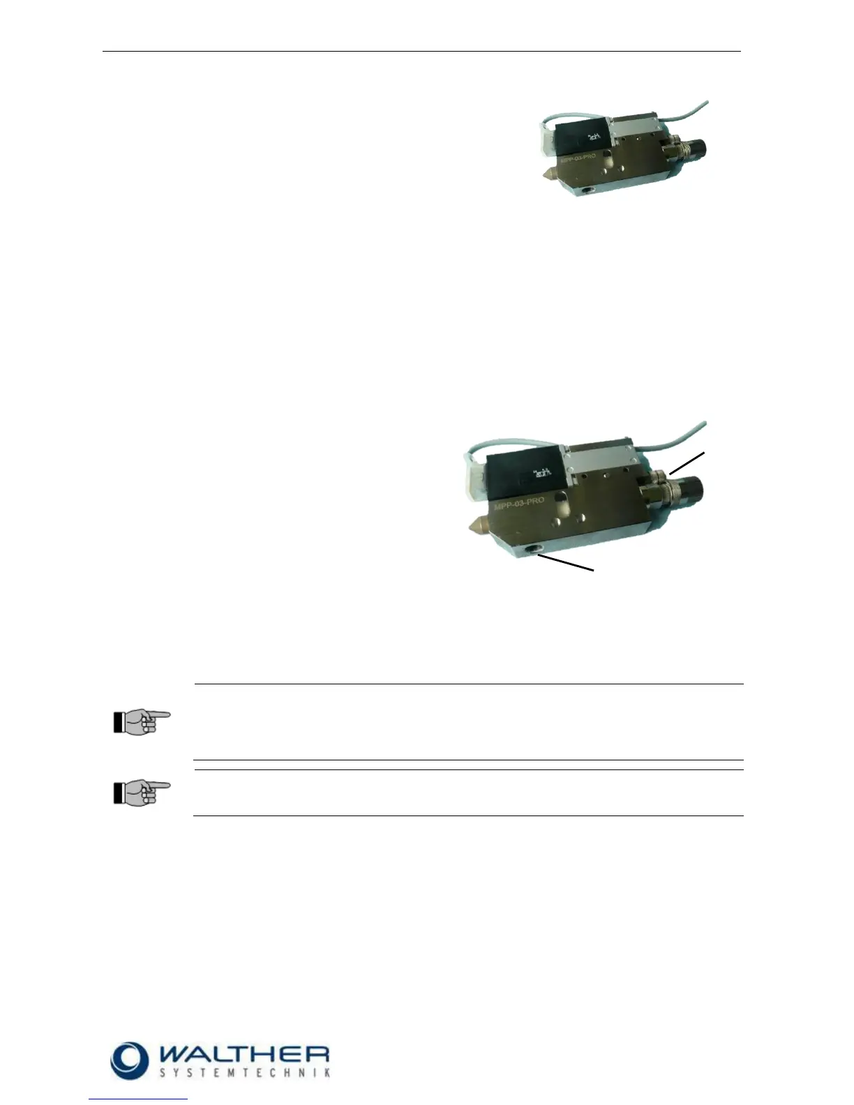
5.2 Hose Mounting
The two function hoses are to be connected as fol-
lows:
1 Control air connection to M5 connection (4.0)
2 Material connection at valve body is 1/8“ fe-
male thread.
5.3 Adjusting the Incomplete Device
The amount of material can be regulated via the stroke adjustment of the needle (7.0). A left turn of the regu-
lating knob increases the material amount. A fine precision thread affects a needle rise that results in an
adjustment of 0.5mm with each turn of the adjusting knob.
IMPORTANT
Do not exceed the maximum turn counter-clockwise of the raster needle locking screw (no
more raster steps noticeable). By then the maximum needle stroke regulation has already
been exceeded.
If you continue turning, the raster needle locking screw will dislocate and jump out!
IMPORTANT
Nozzle and needle can be damaged by wrong handling. Only decrease the material flow by
a right turn of the regulating knob.