WARN® INDUSTRIES PAGE 12 72171 Rev A0
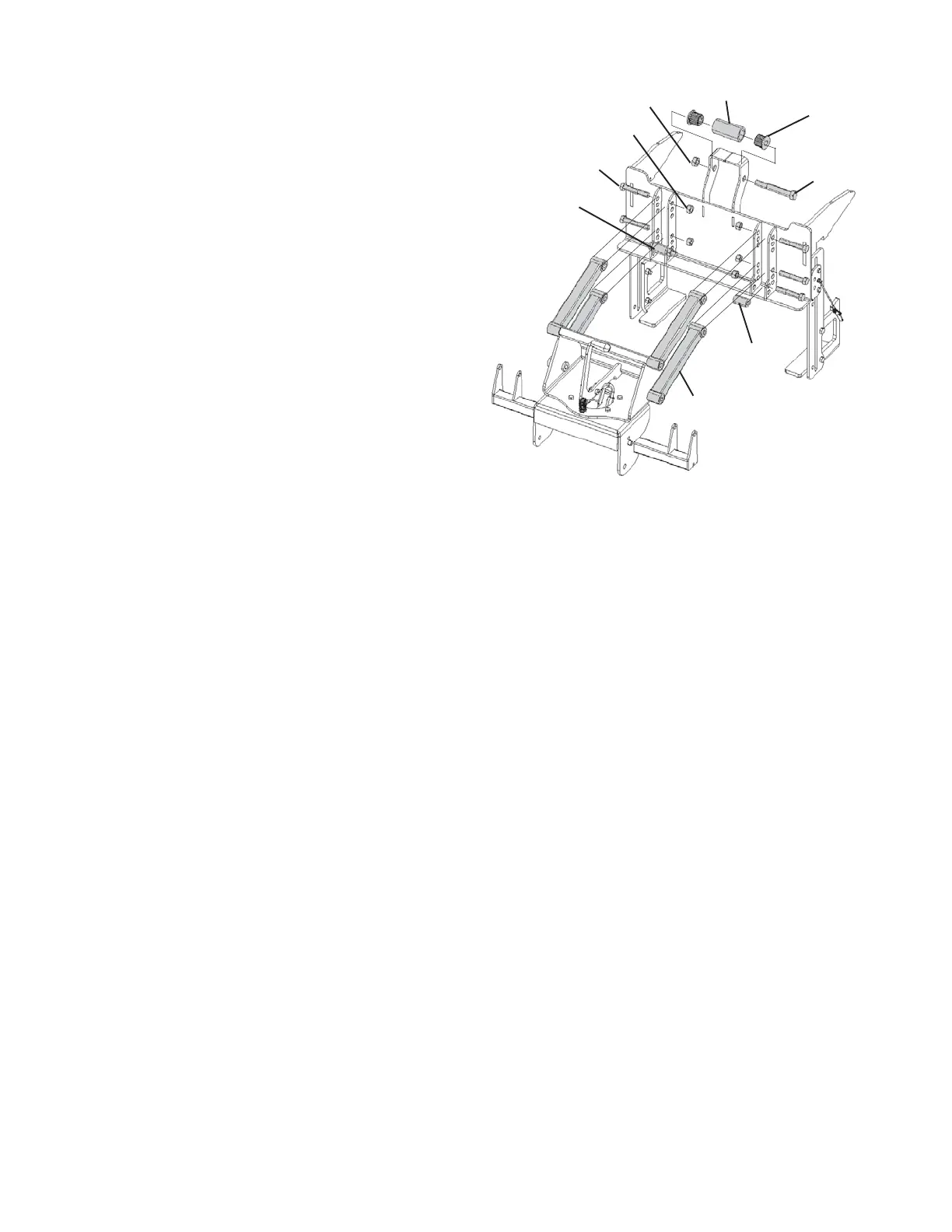
19. Insert a 1” outer dia x 1-5/8” long spacer in arm
stop position #1 between one set of outside
flanges. Slide a 1/2” dia x 3” long bolt through
arm stop position #1 of the outside flange, through
the spacer, and out the other side of the flange.
See Figure 23. Terminate the bolt with a 1/2” dia
nylon lock nut.
20. Place the end of each bottom arm between the
outside flanges and align them to bottom arm
position #1. See Figure 22. Rotate the top arms
up and out of the way if they interfere with the
installation.
21. Slide a 1/2” dia x 3” long bolt through bottom arm
position #1 in the outer flange, through the spacer,
and out the other flange. See Figure 23.
Terminate with a 1/2” dia nylon lock nut. Tighten
the nut until the nut and head of the bolt are
resting against the surface of each outer flange.
The arm should rotate freely around the bolt.
22. Place the end of each top arm between the
outside flanges and align them to top arm position
#1. See Figure 22.
23. Slide a 1/2” dia x 3” long bolt through top arm
position #1 in the outer flange, through the spacer,
and out the other flange. See Figure 23.
Terminate with a 1/2” dia nylon lock nut. Tighten
the nut until the nut and head of the bolt are
resting against the surface of each outer flange.
The arm should rotate freely around the bolt.
5/8 lock nut
(blade not shown)
Roller
5/8x4-1/2
bolt
2x nylon
6x 1/2x3 bolt
2x 1x1-5/8
spacer
4x arms
6x 1/2 lock nut
Assembled stop
Figure 23 Install plow arms and stops onto support