WARN® INDUSTRIES PAGE 13 72171 Rev A0
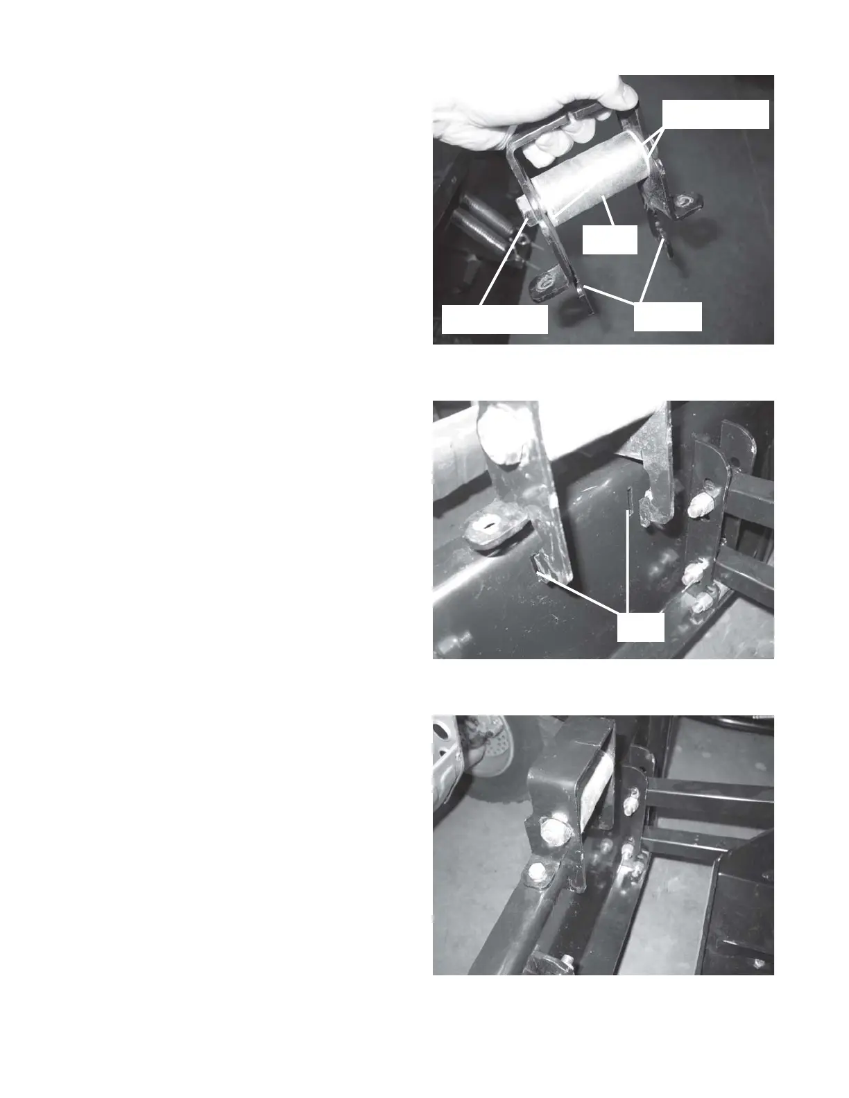
24. Insert two nylon bushings into both open ends of
the roller. Press or slightly tap the bushings into
the roller until they stop. See Figure 24.
25. Insert the roller between the two roller brackets.
Slide a 5/8” dia x 4-1/2” long bolt through one of
the brackets, through the roller and bushings, and
out the other bracket. Terminate the bolt with a
5/8” dia nylon lock nut. See Figure 24. Tighten
until the nut and bolt head are firmly resting
against either side of the flanges, but loose
enough that the roller rotates freely about the bolt.
See Figure 24.
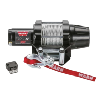
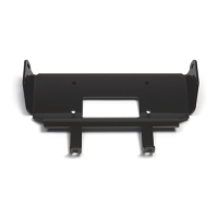
26. Install the assembled guide roller and brackets
onto the plow support by inserting tangs through
slots in the support. See Figure 25.
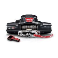
Then rotate guide roller assembly up to align tab
holes to support top flange holes. Fasten with 3/
8” dia x 1-1/4” long bolt and 3/8” dia nylon nut.
See Figure 26.
Figure 24 Assembly of guide roller and brackets
Figure 25 Install guide roller assembly to support
Figure 26 Fasten guide roller assembly at support top flange
Nylon Bushings
Brackets
Roller
5/8” Hardware
Slots