WARN® INDUSTRIES PAGE 9 72171 Rev A0
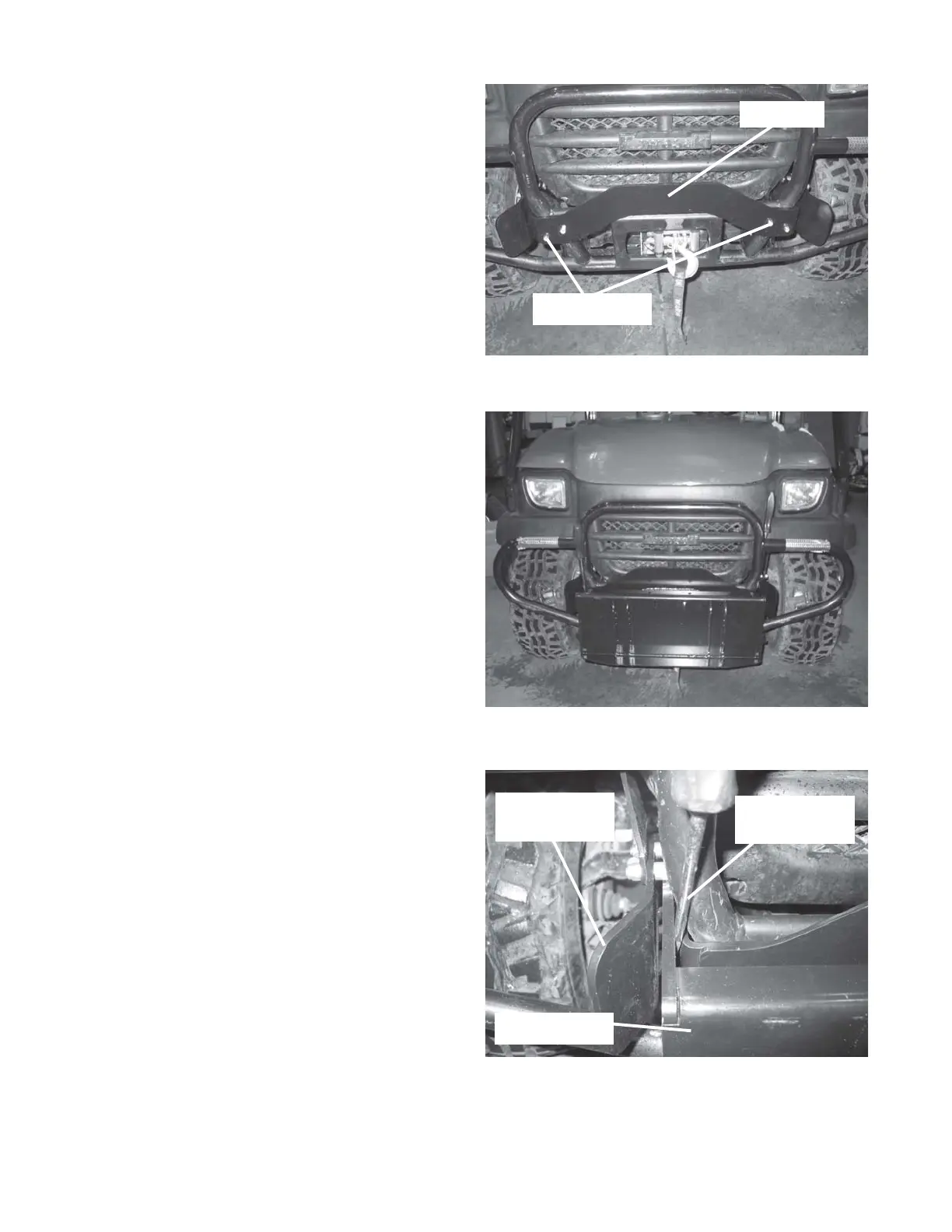
10. Loosely mount the cross brace to the front of the
mounting brackets using 5/16” dia x 1 1/2” wide x
2 1/4” long U-bolt, 5/16” flat washer, and 5/16”
nylon lock nut. See Figure 15. .
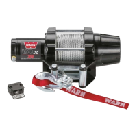
11. Insert the plow support into the mounting
brackets. The mounting brackets should be loose
enough to adjust them side to side to allow the
support to insert. See Figure 16 and 17.
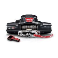
12. With the support inserted into the mounting
brackets, use two screw drivers, one on each
side, to position the mounting brackets centered
on the plow support flanges. See Figure 17.
With the brackets centered to the support and
square to the vehicle and screw drivers in place,
tighten down all mounting hardware in the
following order:
• 7/16” hardware, mounting bracket to frame
• 5/16” dia x 1 1/2” wide x 2 1/4” long U-bolt,
mounting bracket to bumper tube
• 3/8” dia x 2” long carriage bolts, mounting bracket
to brace
• 1/4” x 1” wide x 1 3/4” long U-bolt, brace to upper
frame tube
Screw drivers used for alignment and plow
support can now be removed.
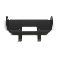
Figure 15 Cross brace mounting.
Figure 16 Install plow support.
Figure 17 Mounting bracket alignment.
Cross Brace
5/16” U-bolt
Screwdriver - both
sides
Mounting Bracket
receiver
Plow Support