Do you have a question about the Warn 80360 and is the answer not in the manual?
Warnings about potential severe injury or death from not following instructions.
Warnings about potential minor or moderate injury from moving parts.
Notice regarding equipment damage and referring to guides for wiring.
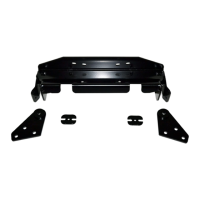
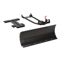
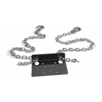
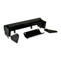
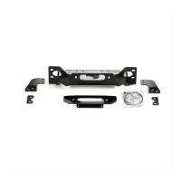
List of all components included in the kit with their reference codes and quantities.
List of necessary tools for installation of the plow mounting kit.
Instructions for securing the plow mounting tabs to the plow.
Steps for installing the winch mount and roller fairlead onto the vehicle.
Final steps for securing the winch, cable, and hook.
Inspect winch, mount, and hardware for wear, rust, or damage before use.
Checking cables for fraying and moving parts for obstructions.
This document outlines the installation and maintenance procedures for a Front Plow Mounting Kit, specifically the Warn Industries 80360 model, designed for Kawasaki Brute Force ATVs. The primary function of this kit is to provide a robust and secure attachment point for a snow plow to the front of the ATV, enabling the vehicle to be used for snow removal or other light-duty plowing tasks. Additionally, the kit is designed to integrate seamlessly with a winch, allowing the winch to be used for lifting and lowering the plow blade, thereby enhancing the ATV's utility.
The Front Plow Mounting Kit serves as an intermediary structure between the ATV's frame and a snow plow blade. It consists of a plow mounting plate, right and left plow mount brackets, and associated hardware. The plow mounting plate is the central component that attaches directly to the ATV's front bumper and frame, providing a stable platform. The plow mount brackets then connect the plow blade to this mounting plate. The design ensures that the forces exerted by plowing are distributed effectively across the ATV's chassis, minimizing stress on any single point.
A key feature of this kit is its compatibility with a winch system. The mounting plate is engineered to accommodate a winch, which is then used to control the vertical movement of the plow. By attaching the winch cable to the plow, the operator can easily raise the plow for transport or lower it for plowing, all from the convenience of the ATV's controls. This integration transforms the ATV into a versatile utility vehicle capable of handling various tasks beyond just recreation. The kit also includes shim plates to ensure proper alignment and a secure fit for the winch mount, optimizing its performance and longevity.
The installation process involves several steps that ensure a secure and precise fit. Initially, the ATV's front bottom skid plate needs to be loosened and rotated down to provide access for installation. The lower bumper bolts are removed, and the plow mount is then positioned and secured using new flange bolts. U-bolts, washers, and lock nuts are used to further secure the plow mount to the ATV's frame tubes, ensuring a strong connection. The instructions emphasize the importance of proper torque specifications for all fasteners to guarantee safety and prevent damage.
Once the plow mount is in place, the winch mount is installed. This involves rotating the winch mount into position within the bumper and aligning it with the plow mount holes. Shim plates are strategically placed to ensure a flush fit. The winch itself is then installed from the left side of the vehicle, with its motor facing the right side, and secured with hardware provided in the winch kit. The roller fairlead, which guides the winch cable, is also attached to the winch mounting plate. Finally, the winch cable is fed through the roller fairlead, and a clevis hook is attached to the end of the cable loop, ready for connection to the plow. The front skid plate is then reinstalled and tightened, completing the mounting process.
The Front Plow Mounting Kit enhances the ATV's functionality by enabling it to perform snow removal and other plowing tasks efficiently. The integrated winch system allows for effortless raising and lowering of the plow blade, reducing physical strain on the operator and improving operational speed. This feature is particularly beneficial in cold weather conditions, where manual adjustments can be cumbersome. The robust construction of the mounting kit ensures that the plow remains securely attached, even when encountering varied terrain or heavy snow loads.
The design prioritizes ease of use and durability. The components are made to withstand the rigors of plowing, including impacts and exposure to harsh environmental elements. The secure attachment points and precise fit minimize vibrations and movement during operation, contributing to a smoother and more controlled plowing experience. The ability to quickly attach and detach the plow (once the mounting kit is installed) means the ATV can easily transition between plowing duties and other recreational or utility uses. The kit's compatibility with specific Kawasaki Brute Force models ensures a tailored fit, optimizing both performance and safety.
Regular maintenance is crucial for ensuring the longevity and safe operation of the Front Plow Mounting Kit and the integrated winch system. The manual explicitly outlines several key maintenance practices.
Firstly, it is recommended to inspect all parts on the winch, winch mount, and related hardware prior to each use. This includes checking for any signs of rust or deformation in the hardware, which could compromise the integrity of the assembly. Any rusted or deformed hardware should be replaced promptly.
Secondly, all nuts and bolts on the winch, winch mount, and related hardware should be inspected for looseness before each use. Loose fasteners can lead to product failure, vehicle damage, and operator injury. Any loose nuts or bolts must be tightened to the specified torque values. Furthermore, stripped, fractured, or bent bolts or nuts must be replaced immediately to maintain structural integrity.
Thirdly, the electrical cables associated with the winch system should be checked for wear or fraying. Damaged cables can pose electrical hazards and impair winch functionality. Any worn or frayed cables should be replaced to ensure safe and reliable operation. The manual also emphasizes the importance of proper cable routing during installation, advising against routing cables across sharp edges, through or near moving parts, or near hot components, to prevent damage.
Finally, all moving and rotating parts of the system should be checked regularly. Debris can accumulate and inhibit the free movement of these parts, affecting performance. Removing any obstructions ensures that all components operate smoothly as intended. The manual stresses that performing regular inspections and maintenance is paramount, and operating the WARN product with damaged or missing parts is strictly prohibited, as it can lead to vehicle damage and operator injury or death. This comprehensive approach to maintenance ensures that the plow mounting kit and winch remain in optimal working condition, providing reliable service for an extended period.
| Part Number | 80360 |
|---|---|
| Product Type | Winch |
| Gear Ratio | 216:1 |
| Gear Type | Planetary |
| Rated Line Pull | 8000 lbs |
| Motor | 12V DC |
| Rope Length | 100' (30m) |
| Rope Diameter | 5/16 in |
| Remote Control | Yes |
| Brake | Automatic |