WARN INDUSTRIES PAGE 8 84855A2
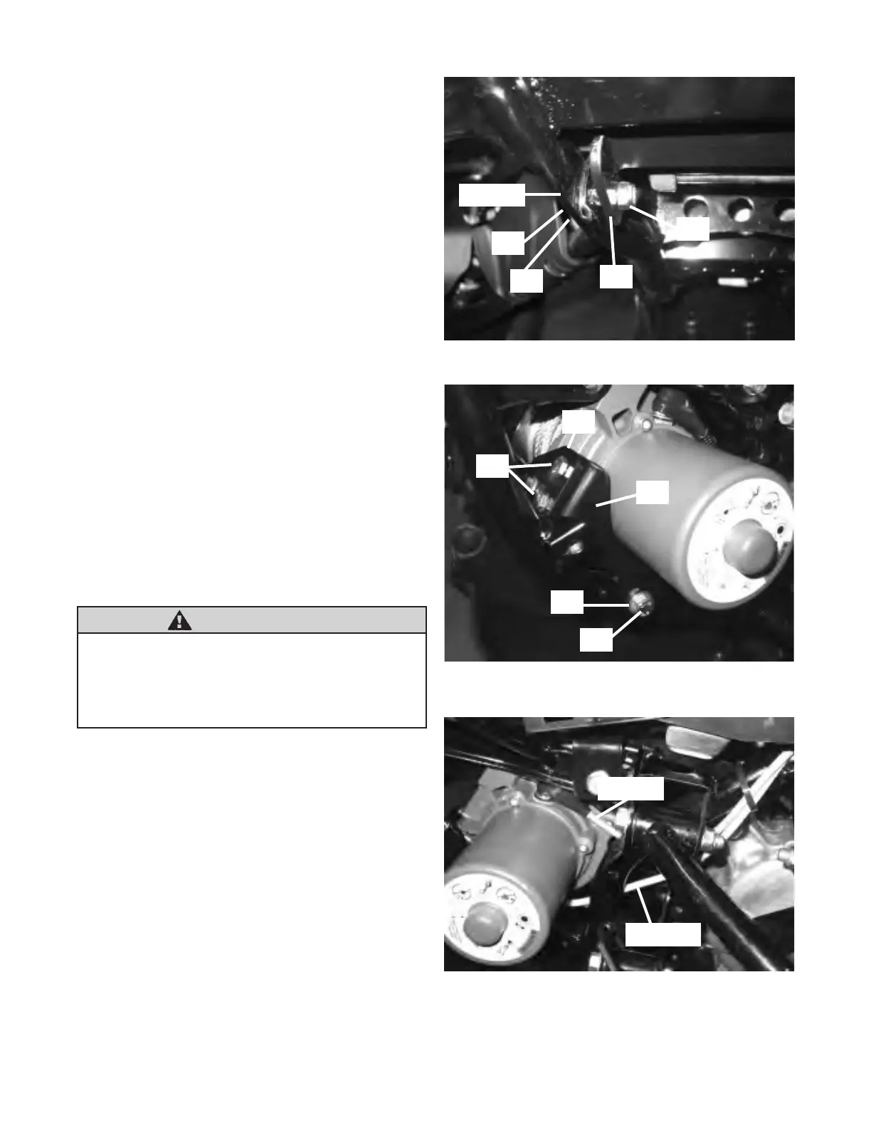
14. Install the supplied 8mm-1.25 x 30mm bolt (B1)
and at washer (B2) into the lower bumper
mounting location. Make sure that the bolt passes
through the hole on the lower mounting bracket
(A2), gure 13. Place the supplied 8mm lock nut
(B6) on the end of the 8mm bolt (B1). Do not
tighten at this time.
15. Place the side mounting bracket (A3) onto the
bottom mounting bracket (A2) and install the two
supplied 6mm-1.00 x 12mm bolts (B4), gure 14.
Place the 6.3mm spacer (B5) between the side
mounting bracket and the bumper. Fasten the
supplied 8mm-1.25 x 30mm bolt (B1) through the
at washer (B2), side mounting bracket, spacer
(B5), bumper, and into the frame, gure 14 and
gure 17. Do not tighten at this time.
16. Place the motor terminal boots on the supplied
yellow and blue electrical cables. Connect the
yellow and blue cables to the motor terminals on
the winch, gure 15. Tighten the motor terminal
nuts to the recommended torque of 5.7 N-m (50
lb-in). Slide the motor terminal boots over the
motor terminals.
B2
B6
B1
A2
Bumper
Figure 13 Lower Bumper Mounting Location
Figure 14 Completed Winch Installation
A3
B1
B2
B4
A2
Figure 15 Connect Yellow and Blue Electrical Cables
Yellow Cable
Blue Cable
WARNING
The 6.3mm (1/4”) spacer must be used to install
the side mounting bracket to the vehicle frame.
Failure to do so can result in product failure
which can lead to vehicle damage and
operator injury or death.