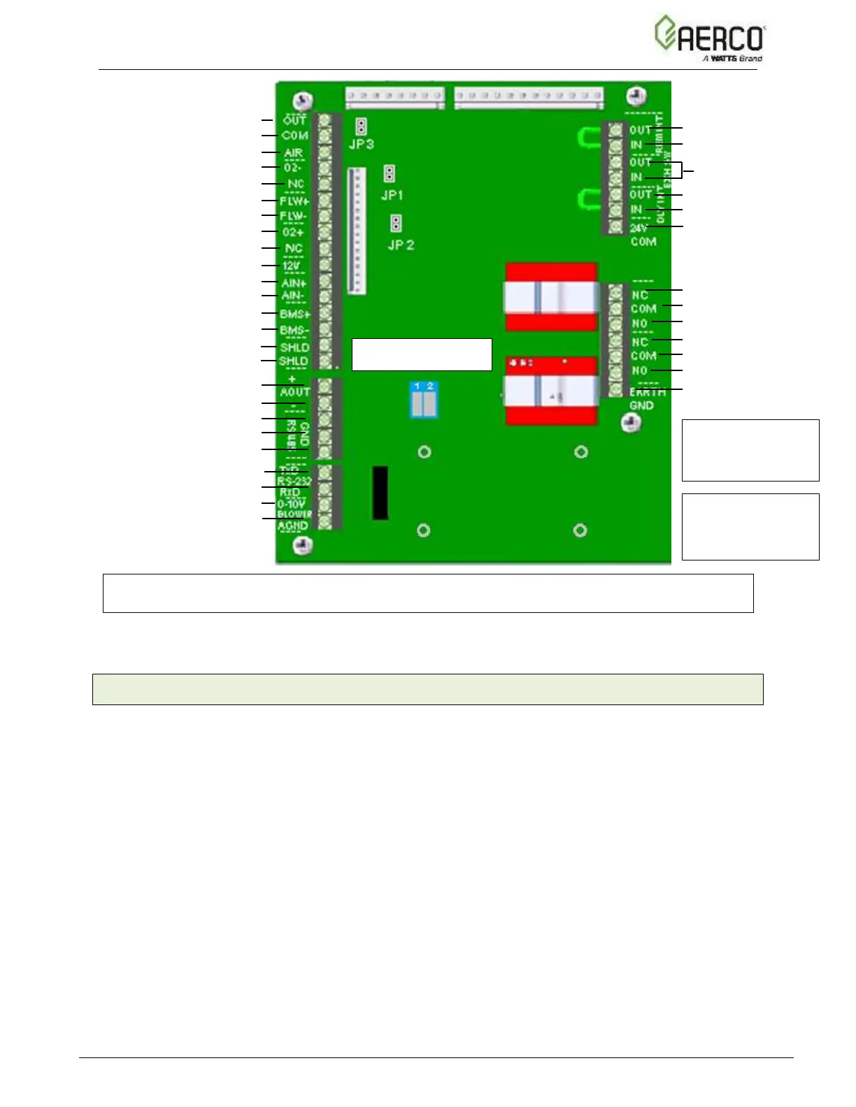
EasyManuals Logo

Watts AERCO Benchmark BMK5000 Installation And Start-Up Manual

Watts AERCO Benchmark BMK5000
62 pages
To Next Page IconTo Next Page
To Previous Page IconTo Previous Page
Page #38 background imageLoading...
Page #38 background image
Benchmark 750-6000 with Edge [i]: Install-Startup Manual
SECTION 2 INSTALLATION
OMM-144_B • GF-217 5/25/2020 Technical Support (800) 526-0288 Mon-Fri, 8 am - 5 pm EST Page 38 of 62
Air
Air Sensor Common
Air Temp Sensor
O2 Sensor
Not Used
Spark Signal +
Spark Signal
O2 Sensor +
Not Used
+12 V Out
Analog In +
Analog In
Valve Feedback +
Valve Feedback
Shield
Shield
Analog Out +
Analog Out
RS-485 +
RS-485 Ground
RS-485 -
RS-232 - TxD
RS-232 - RxD
VFD/Blower +
VFD/Blower
Remote Intl’k OUT
Remote Intl’k IN
NOT USED
Delayed Intl’k OUT
Delayed Intl’k IN
Not Used
Fault Relay N.C.
Fault Relay COMM
Fault Relay N.O.
Aux Relay N.C.
Aux Relay COMM
Aux Relay N.O.
Not Used
NOTE:
Refer to this image for connections rather than the silkscreen labels shown on the board.
Figure 2-11: I/O Box Terminal Strips
2.11.1 Outdoor Air & Air Sensor Common
An outdoor temperature sensor (P/N 61047) is required for the Outdoor Air Reset operating
mode. It can also be used with another mode if it is desired to use the outdoor sensor
enable/disable feature, which allows the boiler to be enabled or disabled based on the outdoor air
temperature.
The factory default for the outdoor sensor is OFF. To enable the sensor, see the Outdoor Air
Temp Sens parameter in the Main Menu Advanced Setup BST Cascade Cascade
Configuration menu.
The outdoor sensor may be wired up to 200 feet (61m) from the boiler. It is connected to the
OUTDOOR AIR and AIR SENSOR COMMON terminals of the I/O board (Figure 2-11). Wire the
sensor using a twisted shielded pair wire from 18 to 22 AWG. There is no polarity to observe
when terminating these wires. The shield is to be connected only to the terminals labeled SHIELD
in the I/O Box PCB. The sensor end of the shield must be left free and ungrounded.
When mounting the sensor, it must be located on the North side of the building where an average
outside air temperature is expected. The sensor must be shielded from direct sunlight as well as
impingement by the elements. If a shield is used, it must allow for free air circulation.
Relay Contacts:
120 VAC, 30 VDC
5 Amps, Resistive
DANGER!
120 VAC USED
IN THIS BOX
DIP 1 Modbus Term
DIP 2 RS232 Enable

Table of Contents

Other manuals for Watts AERCO Benchmark BMK5000

Questions and Answers:

Question and Answer IconNeed help?

Do you have a question about the Watts AERCO Benchmark BMK5000 and is the answer not in the manual?

Watts AERCO Benchmark BMK5000 Specifications

General IconGeneral
BrandWatts
ModelAERCO Benchmark BMK5000
CategoryBoiler
LanguageEnglish

Related product manuals