17
IOM-S-Leak Defense 2211 2022-03-15 © 2022 Sentinel Hydrosolutions, LLC
API INSTALLATIONS
Note 1: The yellow arrow dial, located toward the
center of the API circuit board, needs to be facing F.
Note 2: To test the POL sensor, take a moist paper
towel and touch the 2 metal sensor pins. The Leak
Defense System will go into alarm and the solid-state
relays should turn off the well pump. Push the reset
button on the API before pressing Clear Alarm on the
Leak Defense control panel.
Note 3: When alarm is active, a 6-volt signal is being
applied across each of the solid-state relay’s terminal 3
and 4, from the API. This causes the normally-closed
solid-state relay to open and shut off the pump.
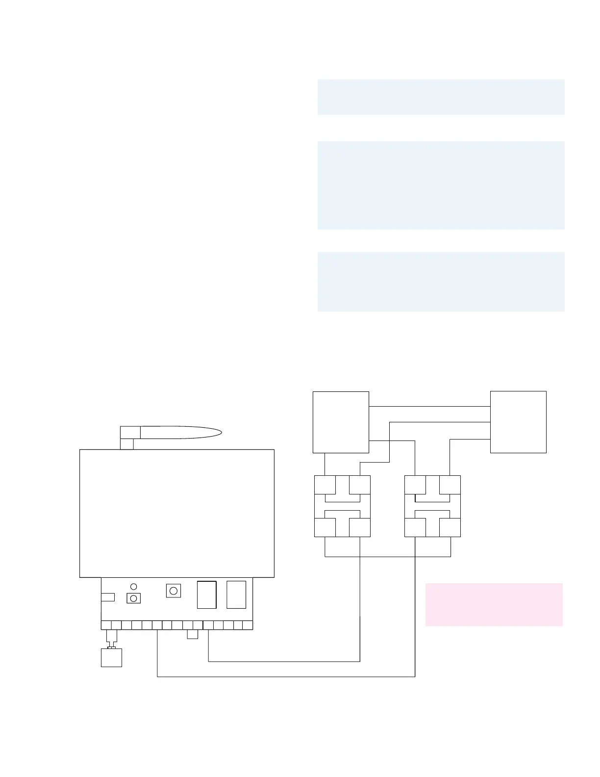
Connecting POL and SS relays
to API
This application is typical for when a 240VAC (up to
50amp) well pump or pressure pump is wanting to be
disconnected when a leak is detected with a POL or when
the LDS valve closes upon suspected water leak.
For terminals 1 and 2 of solid-state relay #1, split a hot leg
of the well pump wire and connect one side of the split
wire to terminal 1 and the other to terminal 2. For terminals
1 and 2 of solid-state relay #2, split the other hot leg of the
well pump wire and connect one side of the split wire to
terminal 1 and the other to terminal 2.
On the API place a jumper between +REF and NO on
either of the API relays.
Wire the solid-state relay input terminals in series as
follows.
Take COM of the same API relay and run a wire to terminal
3 of solid-state relay #1. Then take terminal 4 of solid-state
relay #1 and connect it to 3 of solid-state relay #2, with a
jumper wire. Then take terminal 4 of solid-state relay #2
and run a wire back to –REF on the API.
If you purchased a wired POL, the POLD and GND
terminals of the API get connected to the two wires of
the POL sensor. No connection necessary for wireless
POLD sensor.
SOLID STATE RELAY #1
1
2
4
+3
INPUT
OUTPUT
240VAC
50A
3-32VDC
50A
+3
2
3-32VDC
240VAC
OUTPUT
INPUT
4
1
SOLID STATE RELAY #2
JUMPER
J
J
240VAC OUTLET
WELL PUMP
HOT #1 (H1)
HOT #1 (H2)
NUETRAL (N)
N
N
H1
H1
H1
H1
H2
H2 H2
H2
JUMPER
J
J
B
B
R
R
R
R
B
B
POL
ALARM
NC
COM
ALARM
RELAY #1
NONC
COM
NO
+REF
RELAY #2
HOME/AWAY
MODE SEL
IN+
IN-
STANDBY
LED
IN+
IN-
-REF
POWER
5.5 x 2.1mm
9-12VDC
v+
GND
POLD
TEST PB
7-H/A ENA, STBY ENA, POLD ENA
6-H/A DIS, STBY ENA, POLD ENA
5-H/A ENA, STBY DIS, POLD ENA
4-H/A DIS, STBY DIS, POLD ENA
3-H/A ENA, STBY ENA, POLD DIS
2-H/A DIS, STBY ENA, POLD DIS
1-H/A ENA, STBY DIS, POLD DIS
0-H/A DIS, STBY DIS, POLD DIS
Here are the valid MODE SEL combinations
FOR TECHNICAL SUPPORT:
Please call our office at 1.866.410.1134 – 8:00am to 5:00pm Pacific Time
SEE FIGURE 3 DIAGRAM
PAGE 22

 Loading...