72
First start WAVECOM Decoder W74PC, W-PCI/e, W-CODE, W-CLOUD Manual V9.1.0
In multi-card systems, each card has its own section in the XML file.
The user may edit these files by hand, however it is recommended to use the SAT Frequency Tuning Bar.
The installation package contains example XML files for each mode.
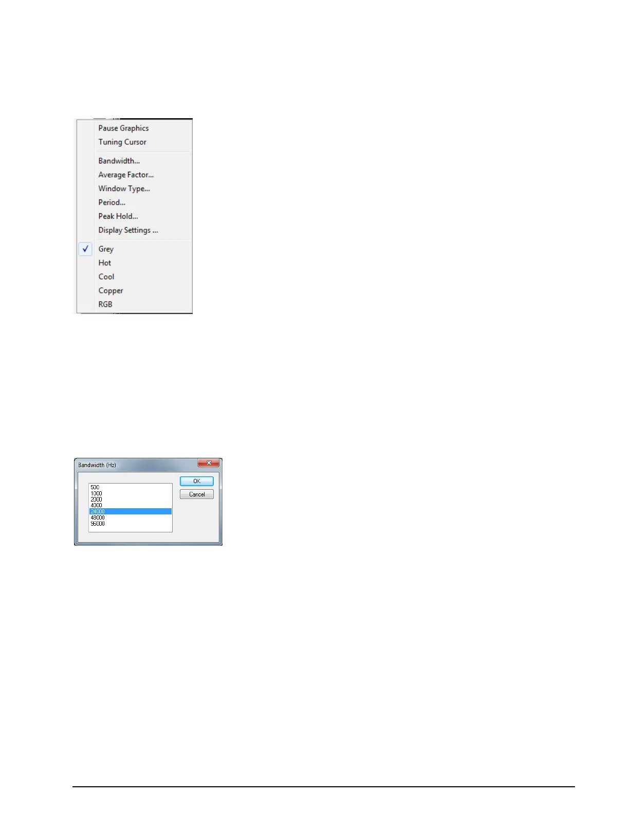
FFT/Sonagram Context Menu
Pause Graphic
Freeze the FFT or Sonagram Window.
Tuning Cursor
Show the 8 green cursor-group in the FFT or Sonagram Window for tuning (multi-carrier) signals.
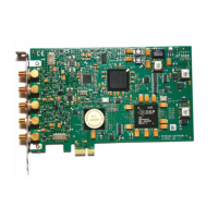
Bandwidth...
To select a display bandwidth use Bandwidth from the context menu or double-click on the Bandwidth:
field on the demodulator status bar. For the Tuning Sonagram / FFT bandwidths of 0.5, 1.0, 2.0, and
4.0 kHz are available. For the Analysis FFT/Sonagram bandwidths of 0.5, 1.0, 2.0, 4.0, 24, 48 and 96 kHz
are available.
Average Factor
After choosing an Average Factor from the context menu, the average of up to 64 measurements may
be displayed at each step. A value of "1" turns averaging off. The averaged display of several measure-
ments is very helpful when monitoring MFSK and FDM transmissions or during heavy fading. The averag-
ing function may also be selected by double-clicking the Avg: field in the upper status bar.
Window Type…
Four window functions Rectangle, Hamming, Hanning and Blackman may be selected. The selection of
a window type influences the accuracy of the signal spectrum measurement. Good frequency resolution is
obtained using the rectangular window, however the rectangular window also causes heavy distortion due
to its poor side-lobe suppression characteristics. A window should be chosen according to the user’s re-
quirements; each window type has its own characteristics as listed below.
The user should be aware that changes in the received signal can cause the display of spurious spectral
lines or aliasing ("false" frequency display) in FFT measurements. Depending on the keying frequency and
the magnitude of the frequency shift, the aliased frequencies may even be stronger than the desired sig-
nal.