CHAPTER 10 CLICK 112/114 109
LEDs
e faceplate of the Click 112/114 has three banks of LEDs. e top bank is used for detec-
tion indication, the second bank menu indication, and the third for menu indication as well
as operation states.
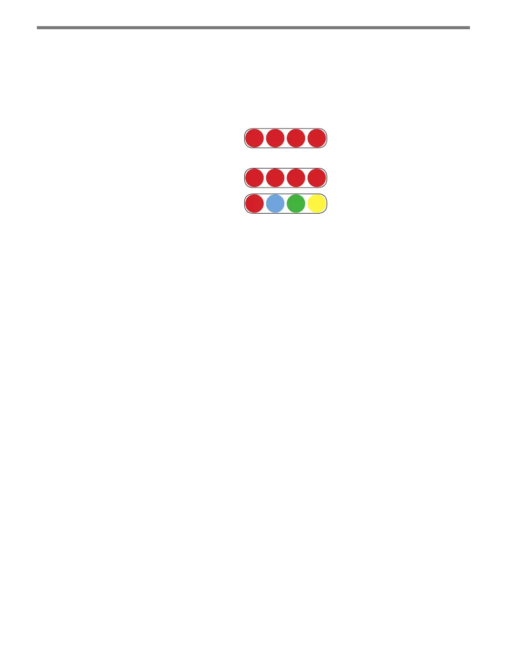
Menu
PWR PU TD RD
Channel
1 2 3 4
1 2 3 4
Figure 10.3 – Click 114 LEDs
e Channel LEDs are detection indicators; they consist of two (Click 112) or four (Click
114) red LEDs numbered 1–2 or 1–4, each representing a channel (see Figure 10.3). An il-
luminated LED indicates that the associated contact is being closed (this can mean either
a vehicle detection or fail-safe mode, which will be discussed later in this chapter). ese
indicators are dedicated to detection and have no other display purposes.
e menu indicator LEDs include two rows of LEDs (see Figure 10.3). e lower row con-
tains Level 1 indicators, while the upper row contains Level 2 indicators. Each level consists
of four LEDs numbered 1–4 (le to right). Level 1 LEDs (the multicolored row) display
which menu item is active. ese Level 1 LEDs are dual-purpose, each indicating both
menu selection as well as a normal operation state when not in Menu mode. e normal
operation state functions include:
Red (PWR) – Indicates the presence of power to the device.
Blue (PU) – is LED is not associated with any general status function and should
remain o while the card is in normal operating mode.
Green (TD) – Indicates serial communication transmit data (from the Click 112/114)
on either RS-485 bus 1 or RS-485 bus 2.
Yellow (RD) – Indicates serial communication receive data (to the Click 112/114) on
either RS-485 bus 1 or RS-485 bus 2.
Level 2 LEDs display conguration options for the menu items selected via the level 1 LEDs.
All level 2 LEDs are red. ese LEDs are dedicated to menu operation, and are extinguished
when the menu is not active.
Installation and Wiring
Use the following steps to install and wire Click 112/114 devices:
1 If you’re using hardware conguration, set all DIP switches before installing Click