110 CHAPTER 10 CLICK 112/114
112/114 devices (covered in the DIP Switches section of this chapter).
2 Insert the cards into the slots on the detector rack. e cards are hot-swappable, mean-
ing they can be inserted and removed while there is still power to the rack.
3 Daisy-chain together all the cards you intend to use in your installation, using short
RJ-11 jumper cables.
4 Connect the rst Click 112/114 card to the SmartSensor via a Click 200 or Click 222
surge protector and a 60” RJ-11 patch cord.
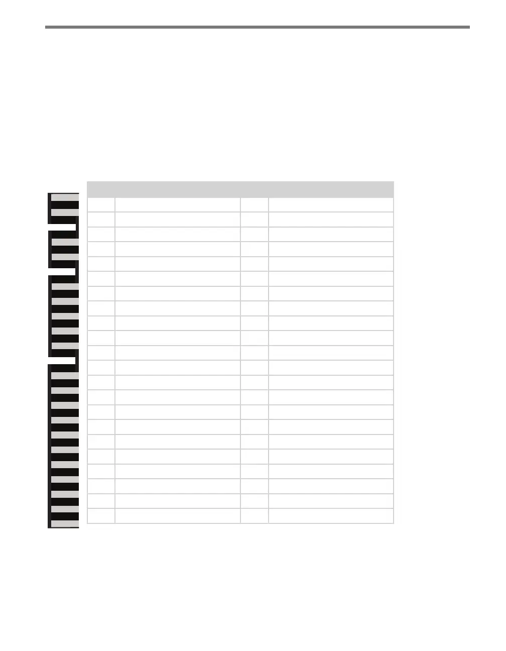
For your information, here is the pinout for the 44-pin edge connector on the back of the
Click 112/114.
Pin Back View Description Pin Front View Description
1 No connection A -DC (common)
2 No connection B +DC (12–24 VDC)
3 No connection C No connection
4 No connection D No connection
5 No connection E No connection
6 No connection F Channel 1 output (+)
7 Channel 1 status output H Channel 1 output (–)
8 No connection J No connection
9 No connection K No connection
10 No connection L Chassis ground
11 No connection M No connection
12 No connection N No connection
13 No connection P No connection
14 No connection R No connection
15 No connection S Channel 3 output (+)*
16 Channel 3 status output* T Channel 3 output (–)*
17 No connection U No connection
18 No connection V No connection
19 No connection W Channel 2 output (+)
20 Channel 2 status output X Channel 2 output (–)
21 No connection Y Channel 4 output (+)*
22 Channel 4 status output* Z Channel 4 output (–)*
* Channels 3 and 4 exist only in the Click 114. In the Click 112, any pin marked
here as being associated with channel 3 or 4 will not be connected to anything.
Table 10.1 – Click 112/114 Pinout