CHAPTER 10 CLICK 112/114 115
Baud Rate
e baud rates for the two RS-485 buses, bus 1 and bus 2 (see the faceplate of the device for
which RJ-11 jacks are for each bus), may be independently congured using the switches
on the second DIP switch, labeled S5.
Note
This parameter can also be changed using the front panel menu or Click Supervisor.
e switch patterns for the two parameters are identical, but bus 1 is congured using
switches 1–3 (S5:1–3) while bus 2 is congured using switches 4–6 (S5:4–6). Also, unlike
the channel input map, there is no dierence between these switches on the Click 112 and
the Click 114.
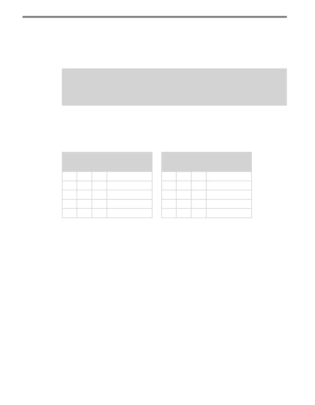
S5: Bus 1 Baud Rate
1 2 3 Value
O O O Software mode
O O On 9600 bps
O On O 19200 bps
O On On 38400 bps
On O O 57600 bps
S5: Bus 2 Baud Rate
4 5 6 Value
O O O Software mode
O O On 9600 bps
O On O 19200 bps
O On On 38400 bps
On O O 57600 bps
Table 10.5 – DIP Switch Baud Rate Settings for Bus 1 (at left) and Bus 2 (at right)
If any switch is on (up), Hardware mode is selected, meaning the baud rate can only be
changed using the DIP switches (as shown in the tables above), and Click Supervisor and
the front panel menu will be able to display the current setting, but not change it.
If all switches are o (down), Soware mode is selected and Click Supervisor and the front
panel menu will be able to both display and change the current setting.
Front Panel Menu
e front panel of the device features a push-button and three banks of LEDs for on-device
conguration and monitoring. e rst bank of LEDs, labeled Channel, displays the state of
the contact closure outputs and is described in the Physical Features section.
e two lower banks of LEDs, labeled Menu, and the push-button, labeled Mode Switch,
are used for navigating through Menu mode. is section will cover how to use the menu
to congure the Click 112/114. e lower bank of LEDs will be referred to as Level 1 and is
used in selecting menu options. e upper bank will be referred to as Level 2 and is used in