146 CHAPTER 13 CLICK 200
Physical Features
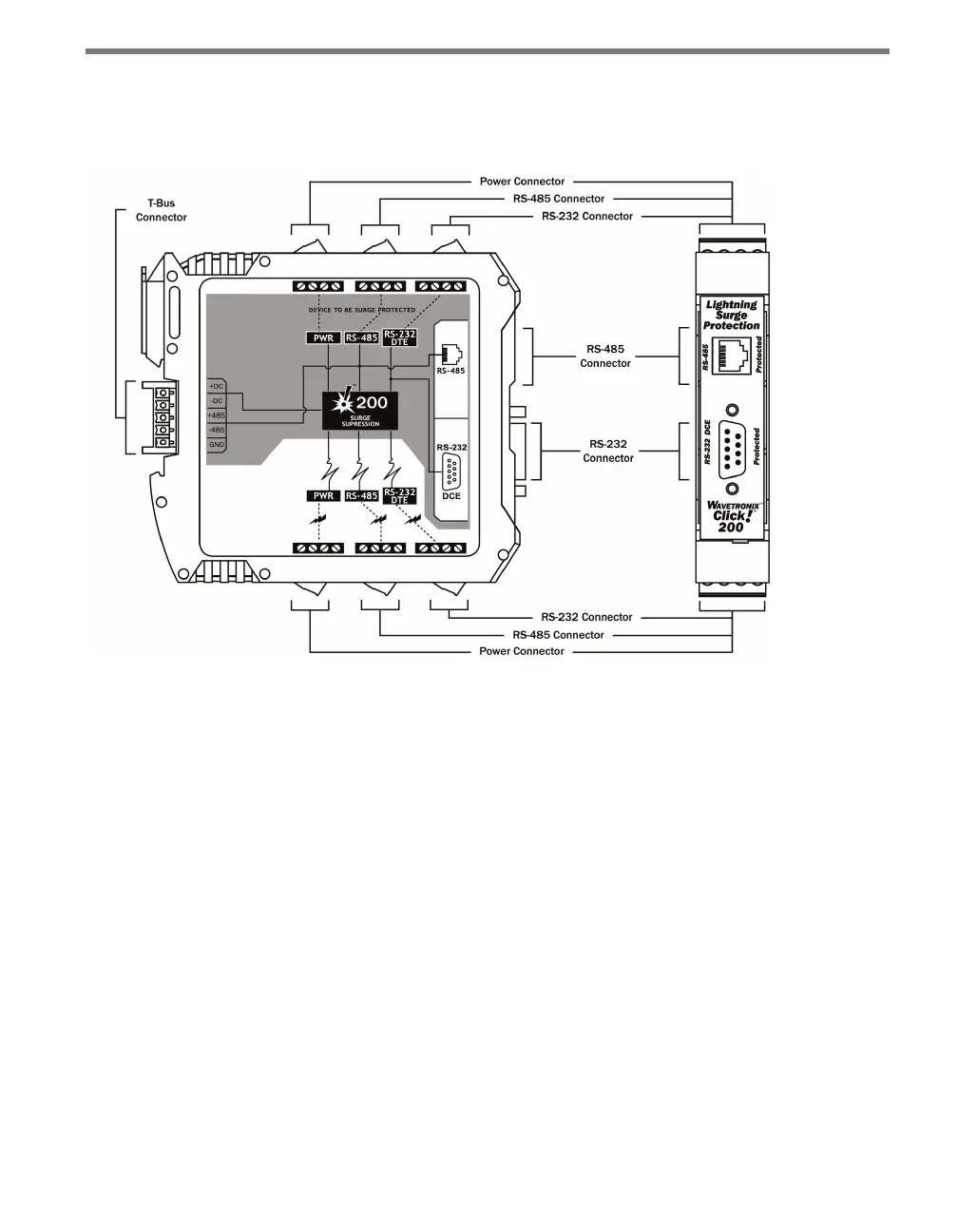
e physical features of the Click 200 include communication and power connections.
Figure 13.2 – The Click 200
Communication Ports
ere are six screw terminal blocks on the 200, each containing four screw terminals. e
three blocks on the top of the module are protected (check for the PROTECTED label to be
sure you have the correct side) and the three on the bottom of the module are unprotected.
ese screw terminal blocks are for wiring power, ground, and communication (RS-232
and RS-485) between the Click 200 and the sensor (or the sensor block, which is in turn
connected to the sensor). ey will be discussed in greater detail in the Installation section
of this chapter.
ere are also two other ways to wire RS-485. e back of the Click 200 features a 5-posi-
tion connector that plugs into a T-bus connector and provides power and RS-485 commu-
nication to the device. It also passes that RS-485 communication to all other devices on the
T-bus. In addition, the faceplate of the Click 200 features an RJ-11 jack for RS-485 com-
munication. is jack can be used to connect a jumper cable from the Click 200 to contact
closure cards or to another device that uses RS-485 communication.
e front of the device also features a DB-9 connector for RS-232 communication.