152 CHAPTER 14 CLICK 201/202/204
Physical Features
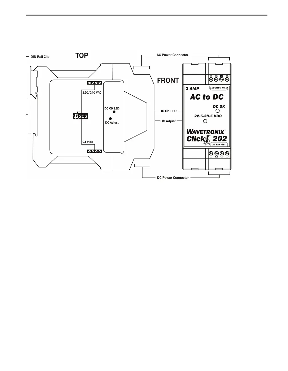
Click 201/202/204 modules have the following physical features.
Figure 14.2 – Diagram of the Click 202
Click 201/202/204 modules are wired through the pluggable screw terminal blocks on the
top and bottom of each module. e top block has either two or four screw terminal con-
nections for wiring AC in. DC out is wired through the bottom of the module. e Click
202 and 204 feature one screw terminal block on the bottom of the module, while the Click
201 has two. e screw terminal blocks are red-keyed, allowing them to plug only into their
proper slots.
Click 201/202/204 modules also have a green activity indicator light marked DC OK on the
faceplate. is light glows steadily when the module is working properly, but will go out if
the power supply is interrupted or if the DC connection is shorted.
Finally, the devices also have a potentiometer, marked “22.5–28.5 V DC,” located on the
faceplate beneath the LED. is can be used to set the DC output voltage. Insert a small
screwdriver into the hole and twist clockwise to raise the voltage and counterclockwise to
lower it. Voltages from 22.5–28.5 VDC are allowed. Change this setting only if instructed to
do so by Wavetronix Technical Services.
Installation
e Click 201/202/204 devices are wired through the pluggable screw terminal blocks lo-
cated on the tops and bottoms of the modules. Refer to the tables and gures below to cor-