164 CHAPTER 17 CLICK 211
Note
Wiring the Click 211 from the power plant requires the use of two twin terminal blocks.
Physical Features
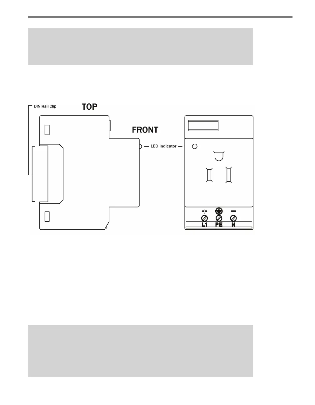
Figure 17.2 – Diagram of the Click 211
e Click 211 has three screw terminal connections, located on the top of the module, for
wiring in power. ere is also an LED located on the front of the module; this LED lights up
when the Click 211 is working properly.
Installation
Installing the Click 211 involves a slight change in how your installation’s power plant is put
together. Follow these steps to wire the power plant and Click 211.
Note
The pictures below show the Click 211 being installed on a backplate as part of a cabi-
net installation. It is not necessary to use a backplate, however, and if you are not,
the wiring will still be the same.