166 CHAPTER 17 CLICK 211
Figure 17.4 – Wiring into the Power Supply
8 Wire power out of the Click 201/202/204 as described in Chapter 1.
Wiring the Click 211
1 Attach a 14 AWG wire that is stripped 3/8” on both ends (green is standard) to the
screw terminal marked G on the OUT side of the Click 230.
2 Attach 14 AWG wires that are stripped 3/8” on both ends to the last set of ports on the
two twin terminal blocks, following the coloring of the wires attached to each block.
3 Snap the Click 211 onto a DIN rail within reaching distance of the device to be plugged
in. e device cannot be mounted over a T-bus.
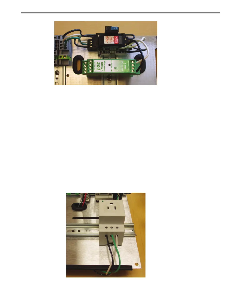
4 Terminate the line (black) wire into the screw terminal on the Click 211 marked L1.
5 Terminate the ground (green) wire into the screw terminal on the Click 211 marked
PE (protective earth).
6 Terminate the neutral (white) wire into the screw terminal on the Click 211 marked N
(see Figure 17.5).
Figure 17.5 – Properly Wired Click 211