220 CHAPTER 26 CLICK 330/331
Physical Features
Click 330/331 modules have several Ethernet ports, allowing you to create a quick Ethernet
network by simply connecting Ethernet cables.
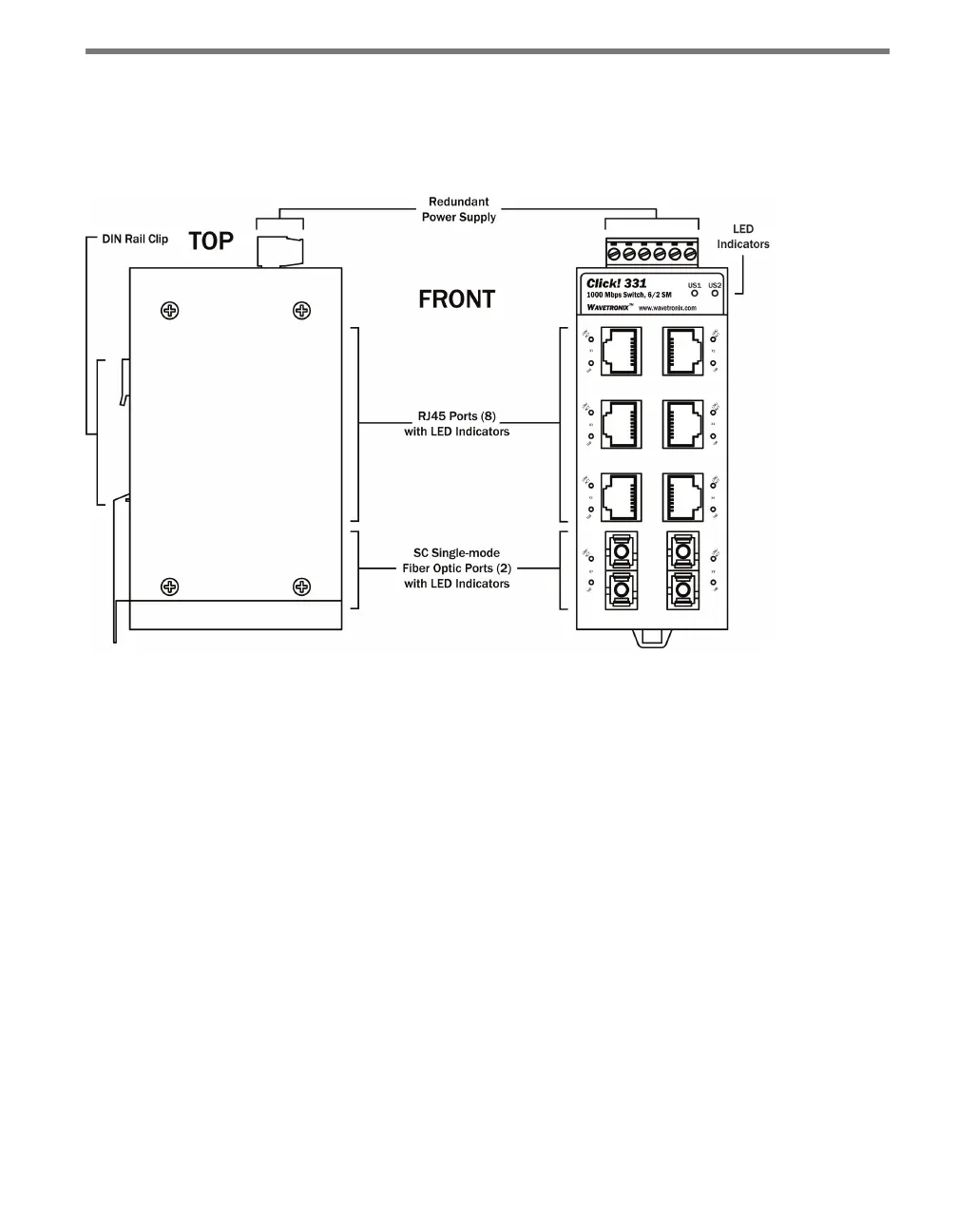
Figure 25.2 – Diagram of the Click 331
Screw Terminals
e top of the Click 330/331 contains a screw terminal block, with a total of six screw ter-
minal connections. e screw terminal block allows you to wire a power supply (US1 and
GND), a redundant power supply (US2 and GND) and alarm notices (R1 and R2).
Ethernet/Fiber Optic Ports
e Click 330 and 331 feature the following physical Ethernet and ber options:
Click 330 – Unmanaged switch with eight RJ-45 ports.
Click 331 – Unmanaged switch with six RJ-45 and four ports for connecting ber optic
cables. ese ports can be used to extend the segment length up to 20 km.
LEDs
e Click 330/331 have three dierent kinds of LEDs.
At the top of each device are two green LEDs labeled US1 and US2, used for monitor-
ing the power supply (see Table 25.1). US1 monitors the main power supply and US2
monitors the second (redundant) power supply.