22 CHAPTER 3 WIRING THE DEVICES
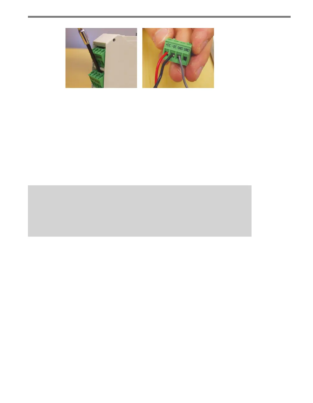
Figure 3.1 – Removing and Wiring Screw Terminal Blocks
RS-485 Communication
Another feature that is common to many Click devices is RS-485 communication capabili-
ties. RS-485 is important for Click devices because it is carried on the T-bus to all the Click
devices on a given DIN rail.
Connecting RS-485 communications to the Click devices on a DIN rail can be accom-
plished in two dierent ways: through a 5-screw terminal on the end of a T-bus, or through
a Click module, which will then communicate with the T-bus.
Note
The steps in this section are specifically for use with a Wavetronix SmartSensor ca-
ble. If you are using a dierent cable or wiring system, the colors of the wires used
will be dierent.
To connect through a 5-screw terminal, follow these steps.
1 Connect the +485 (white) wire from the terminal block or cable to the middle screw
terminal on the 5-screw terminal block connector you’re using for the T-bus in question
(see Figure 2.2 in the previous chapter for the pinout of the 5-screw terminal block).
2 Connect the -485 (blue) wire from the terminal block or cable to the middle screw
terminal on the 5-screw terminal block.
3 Plug the 5-screw terminal block into the T-bus.
To connect through any Click device with RS-485 ports, follow these steps:
1 Ensure that the Click device is mounted on a T-bus connector.
2 Connect the +485 (white) wire from the terminal block or cable to the terminal marked
“+485” in the screw terminal blocks (see Figure 3.2).
3 Connect the -485 (blue) wire from the terminal block or cable to the terminal marked
“-485” in the screw terminal blocks.
4 Connect the RS-485 drain wire from the terminal block or cable to a GND terminal in
the screw terminal blocks.