230 CHAPTER 28 CLICK 400
Physical Features
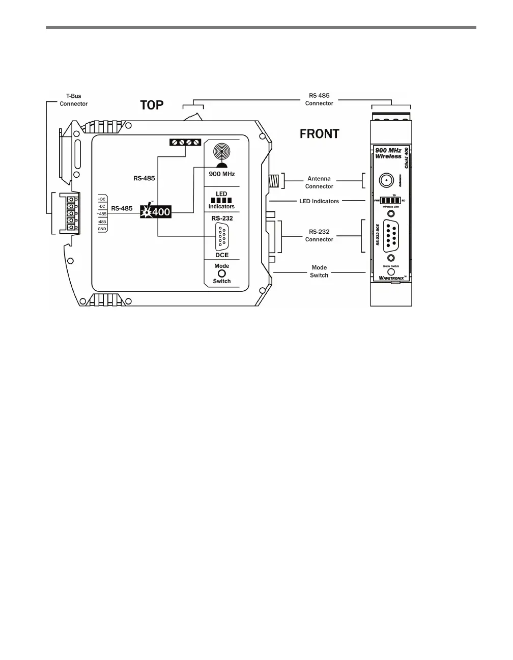
e Click 400 has several communication ports, as well as features for conguration.
Figure 27.2 – Diagram of the Click 400
Communication Ports
e back of the Click 400 features a 5-position connector that plugs into a T-bus connector
and provides power and RS-485 communication to the device. It also passes RS-485 com-
munication from the Click 400 to all other devices on the T-bus.
e top of the device has a pluggable screw terminal block that features four terminals—one
-485, one +485 and two grounds—for wiring RS-485 communication. is screw terminal
block can be removed for easy preinstallation wiring. It will not be necessary, however, to
wire RS-485 through the screw terminal block if the device is connected to a T-bus with
uninterrupted RS-485 communication.
e front of the device has a DB-9 connector for RS-232 communication. Connect a straight-
through cable from this port to a computer to congure the device using Click Supervisor.
Any data on one port will be transmitted simultaneously on all other ports.
Antenna
e Click 400 has a reversed polarity SMA antenna connector. An external antenna can be
mounted on the exterior of the trac cabinet or up on a pole for maximum range. A whip
antenna can also be used inside the cabinet. If the antenna is installed inside a metal cabi-
net, the range will be diminished.