CHAPTER 28 CLICK 400 231
Configuration Features
e faceplate of the Click 400 has the following four LEDs:
PWR (red) lights up when the device has power.
Wireless Link (blue) lights up when the device is set to be a client and can see a server.
If the device is set up to be a server, this LED will blink.
TD (green) lights up when the device is transmitting data.
RD (yellow) lights up when the device is receiving data.
e LEDs are also used to indicate operation modes, which will be discussed later in the
On-device Conguration section of this chapter.
e front also has a push-button labeled Mode Switch, which is used to cycle the Click 400
through operation modes. is will be discussed in the On-device Conguration section
of this chapter.
On-device Configuration
e Click 400 can be congured using the push-button on the lower part of the faceplate.
Press and hold the push-button to cycle through the dierent operation modes; release the
button when the desired mode is reached. A quick press and release of the push-button will
exit out of any mode and return the unit back to normal operation. Table 27.1 and the fol-
lowing sections describe the dierent operating modes.
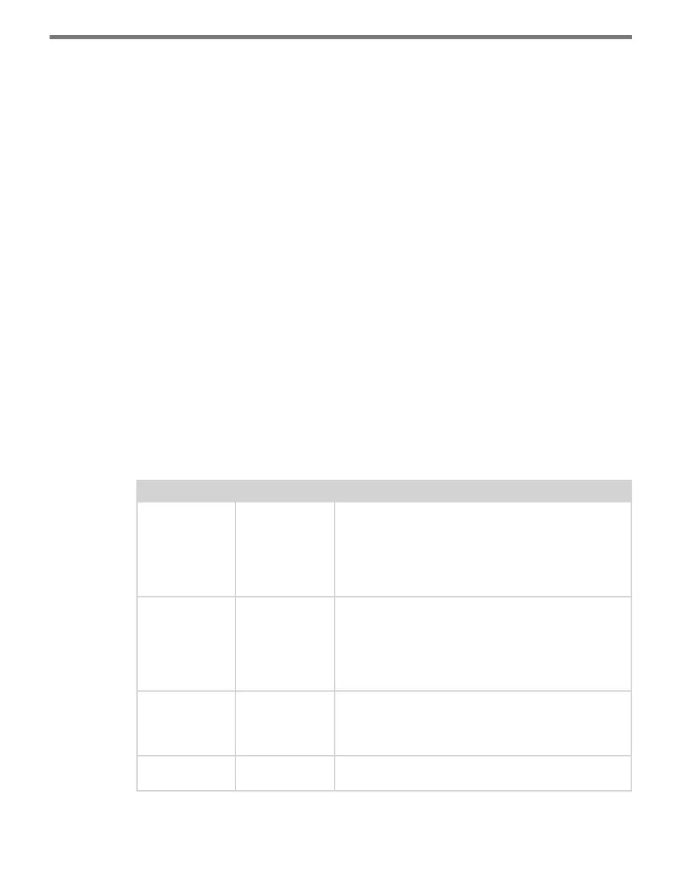
Mode LED Definition
Autobaud Green (solid) To autobaud the Click 400, press the push-button, then
release when the green LED turns on. The Click 400 is
autobauding when the green LED is on and the red LED
is blinking. When it is finished autobauding, the red LED
will turn on. If you autobaud a Click 400, the device will
always be set up as a client.
Link Test (Client) Blue (solid) To set the Click 400 in Link Test mode as a client, press
the push-button, then release when the blue LED turns
on. If the yellow LED is blinking, then the module is
receiving data out of sequence (missing some data). If
the green LED is blinking, then the module is receiving
all data in order.
Link Test (Server) Blue (flashing) To set the Click 400 in Link Test mode as a server, press
the push-button, then release when the blue LED is
blinking. The Click 400 is transmitting data if the red
and blue LED stay on and the green LED blinks.
Reset Red (flashing) To reset the Click 400 to factory defaults, press the
push-button, then release when the red LED is blinking.
Table 27.1 – Click 400 Operation Mode Definitions