CHAPTER 28 CLICK 400 233
ashing. e red LED should be solid and the green and yellow LEDs will ash. Wait for a
few seconds and the device will now have the original factory conguration.
Computer Configuration
e Click 400 can be congured more exactly using the Click Supervisor soware. See
Chapters 4 and 5 of this document for instructions on how to download and install Click
Supervisor and how to connect to your device using the soware.
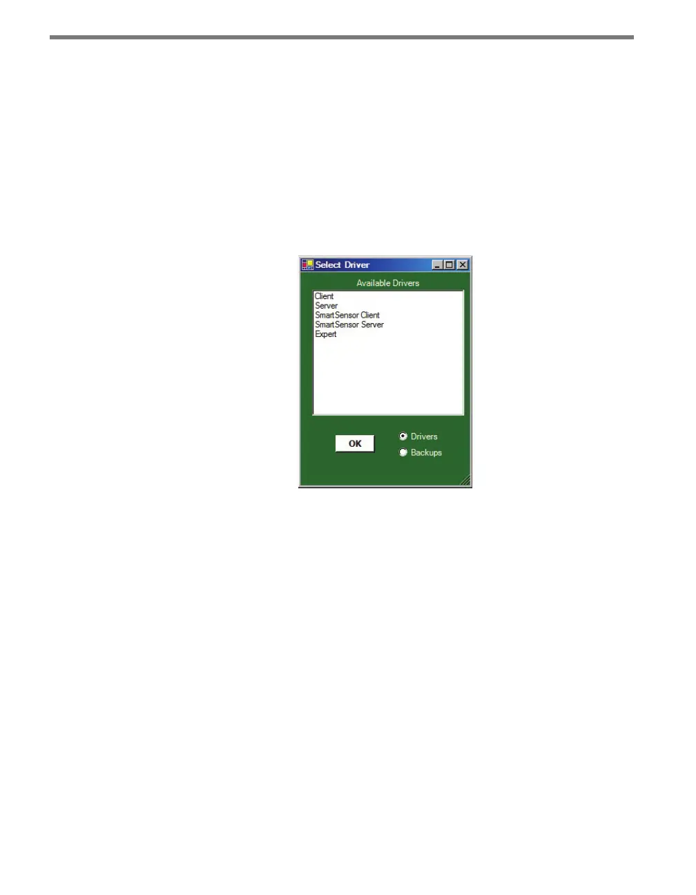
e Click 400 can be congured using one of ve drivers (see Figure 27.3).
Figure 27.3 – Selecting a Driver
Which driver you use will depend on what you need to use the device for. e rst four
drivers are known as application drivers and are used to set the Click device to work in
specic applications. Use the list below to nd the appropriate driver for your application:
Client – If you intend to connect multiple clients to a single server, use the Client driver.
Server – If you intend to connect a single radio to another single radio, use the Server
driver.
SmartSensor Client – If you intend to connect a wireless sensor station to a wireless
base station, use the SmartSensor Client driver.
SmartSensor Server – If you intend to connect a wireless base station to a wireless sen-
sor station, use the SmartSensor Server driver.
To see advanced settings, use the Expert driver. is driver, which exposes every available
eld for the Click 400, should only be used under the direction of Wavetronix Technical
Services.
Aer you have made conguration changes on a driver and saved it to the Click device, the
word “current” will appear aer that driver to indicate the driver that is currently loaded