44 CHAPTER 6 CLICK 100
Physical Features
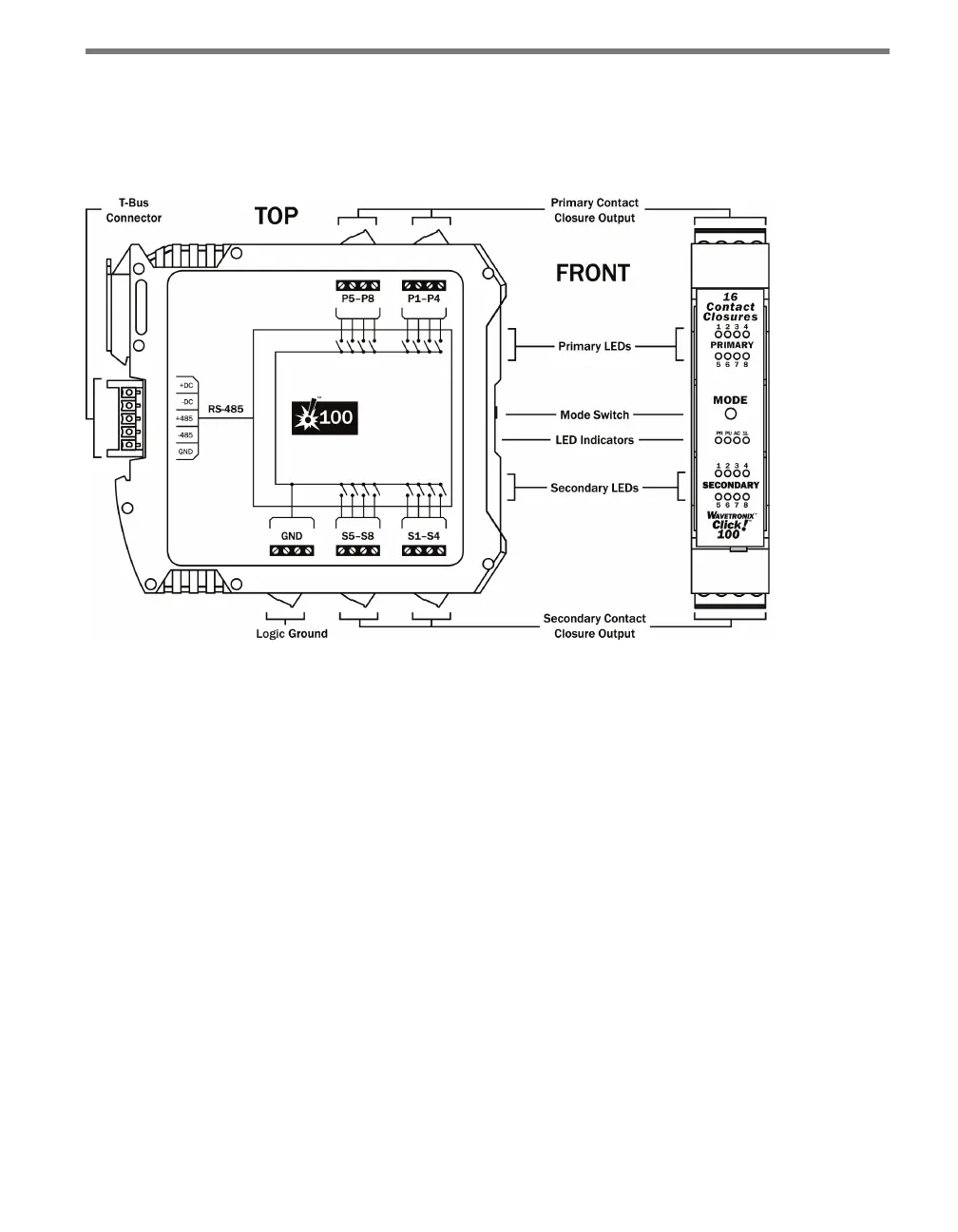
e Click 100 has eight primary and eight secondary contact outputs, which all share a logic
ground (see Figure 6.2).
Figure 6.2 – Diagram of Click 100
Communication Port
e back of the Click 100 features a 5-position connector that plugs into a T-bus connector
and provides power and RS-485 communication to the device. It also passes RS-485 com-
munication from the Click 100 to all other devices on the T-bus when pressing the Mode
button during conguration (see the On-device Conguration section of this chapter for
more information).
Screw Terminals
e contact closure outputs are wired to a controller, data logger or BIU (Bus Interface
Unit) using the pluggable screw terminals on the top and bottom of the Click 100. e top
screw terminals are labeled 1–8 and represent the primary outputs. Primary 1 (P1) repre-
sents the lane closest to a side-re SmartSensor and the remaining outputs represent the
lanes as they sequentially get further from the sensor. For dual-loop emulation, the contact
closure outputs must be wired with the primary always leading the secondary (see Figure
6.3).