CHAPTER 6 CLICK 100 45
Figure 6.3 – Primary and Secondary Outputs
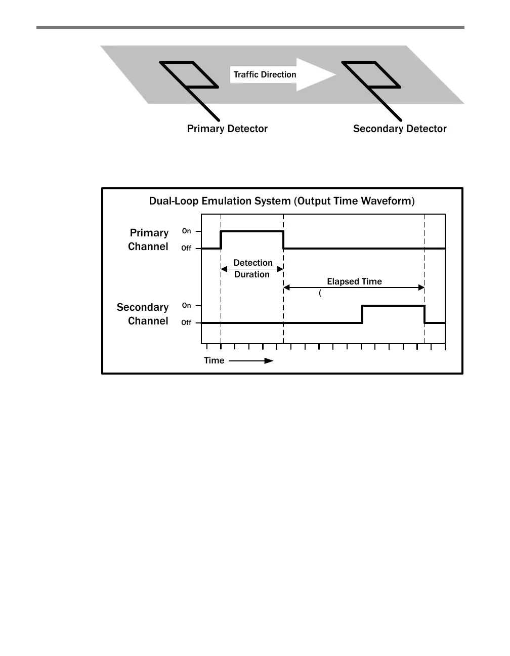
Figure 6.4 below shows a diagram of the output signal time waveforms of the two detectors.
Dual-Loop Emulation System (Output Time Waveform)
Indicates Speed)
Figure 6.4 – Emulation System Output Waveforms
e bottom screw terminals are also labeled 1–8 and represent the secondary outputs, with
secondary one (S1) representing the lane closest to the SmartSensor. e remaining four
screw terminal connections are labeled GND and are a common logic ground for all 16
contact closure outputs. You must provide a connection from the GND terminals to a logic
ground to make the primary and secondary outputs operational.
e screw terminal connectors can also be unplugged from the Click 100 allowing you to
pre-wire the Click 100 before nal installation.
Configuration Features
e four LEDs located right below the push-button are used to indicate operation modes,
which will be discussed later in the On-device Conguration section of this chapter. Below
is a list of the four LEDs:
PR (Presence) – Red
PU (Pulse) – Orange