46 CHAPTER 6 CLICK 100
AC (Actuation) – Green
1L (One Loop Speed) – Yel low
e front also has a push-button labeled Mode Switch, which is used to cycle the Click 100
through operation modes. is will be discussed in the On-device Conguration section.
LEDs
e Click 100 module has sixteen contact closure outputs. Each output represents a prima-
ry or secondary channel and has a corresponding LED on the front of the Click 100 module.
e eight red LEDs on the top of the faceplate correspond to the primary outputs and the
eight yellow LEDs on the bottom of the faceplate correspond to the secondary outputs.
On-device Configuration
e Click 100 can be congured using the push-button in the middle of the faceplate.
To automatically congure the Click 100, press and hold the push-button until the green
LED ashes four times. e green LED and contact closure LEDs will ash during the auto-
conguration process, which normally takes 5–30 seconds. e auto-conguration process
matches the Click 100 with the sensor’s baud rate, loop size and loop spacing.
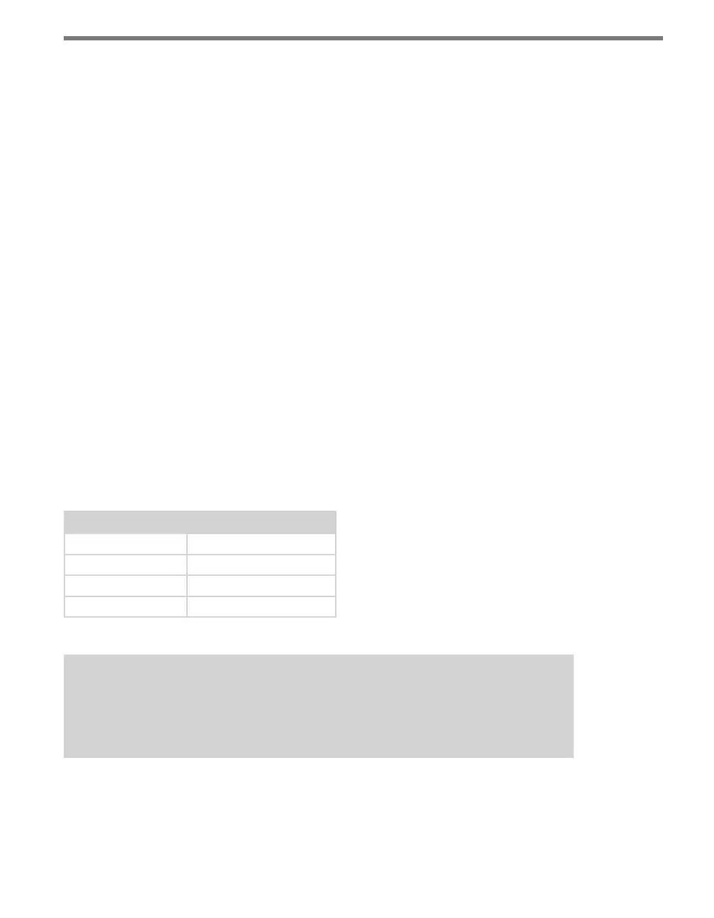
e rst four primary LEDs indicate the current baud rate at which the Click 100 is trying
to congure. e following table shows what the dierent ashing LEDs represent:
Primary LED Baud Rate
1 9400 bps
2 19200 bps
3 38400 bps
4 57600 bps
Table 6.1 – List of Baud Rates
Note
The maximum baud rate that can be used is 57600. If the sensor’s RS-485 bus is set
higher than 57600, no data will be seen on the Click 100.
e yellow LED will ash four times indicating the end of the auto-conguration process.
Once the Click 100 is congured, the device will be set to Presence (PR) mode.
Press the push-button until the desired operation mode is selected.