CHAPTER 7 CLICK 101 53
Note
After you have completed programming the device using Click Supervisor, remove
the RS-232 serial cable from the DB-9 port. This will prevent computer equipment
(like docking stations) from holding the RS-232 TD line high. If the TD line is inadver-
tently held high, the Click 101 will transmit on the RS-485 bus, but will not receive any
data from connected sensors.
Like many of the other Click devices, the Click 101 also acts as an RS-232 to RS-485 con-
verter. To disable the normal polling routine and enable serial conversion, a passcode mes-
sage must rst be sent over one of the ports. SmartSensor Manager automatically sends
a passcode message when a connection is made to a side-re sensor. is allows you to
congure any of the sensors on the RS-485 bus via the DB-9 connector on the front of the
Click 101. e normal polling routine will resume operation aer 10 seconds of inactivity
on the ports. SmartSensor Manager HD sends a passcode message once every few seconds
to keep the normal polling routine of the Click 101 suspended. SmartSensor Manager for
the 105 sensor only sends passcode messages on some screens, so you may run into situa-
tions where normal polling will resume while connected to a 105 sensor.
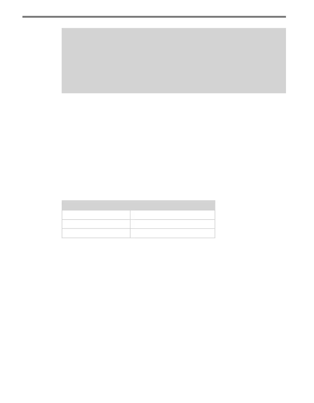
e passcode message can be one of those shown in Table 7.1:
C String Format Hex Byte Format
“X5/r” 0x58 0x35 0x0D
“Z1/r” 0x5A 0x31 0x0D
“Z2/r” 0x5A 0x32 0x0D
Table 7.1 – Passcode Messages that Enable Serial Conversion
LEDs
e Click 101 faceplate contains 16 LEDS. During normal polling, each LED lights up when
the associated digital output is active.
If normal polling is suspended and the device is powered, the PWR (red) LED will light up
and the RD (yellow) LED will activate each time data is received on a communication port.
e TD (green) LED will not activate each time data is transmitted on a communication
port. e green LED is used during normal polling to indicate that output 15 is active, and
it is also used during manual conguration to select the autobaud conguration task.
Screw Terminals
e screw terminals labeled 1–16 on the top and bottom of the Click 101 are contact closure
outputs that can be connected to a trac controller or data logger. ese digital outputs are
contact closure outputs that require a logical ground connection.