52 CHAPTER 7 CLICK 101
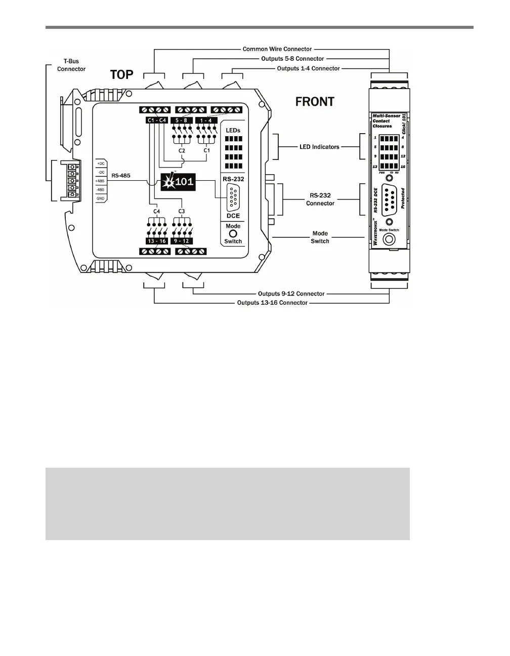
Figure 7.4 – Diagram of the Click 101
Communication Ports
e back of the Click 101 features a 5-position connector that plugs into a T-bus connector
and provides DC power and half-duplex RS-485 communication to the device. e RS-485
communication port on the T-bus allows the Click 101 to serve as the polling master on a
multi-drop RS-485 bus. e sensors act as clients on the RS-485 bus, only responding to
requests from the Click 101. Any devices connected to the T-bus will also have connectivity
over the shared RS-485 lines; however, when a Click 101 is being used, it is expected that
none of the sensors or other devices on the bus will push data. is will help avoid com-
munication message collisions on the RS-485 bus.
Note
It is recommended that the sensors not be connected to the T-bus while program-
ming this device with Click Supervisor.
e front of the Click 101 features a DB-9 connector for RS-232 communication. is con-
nector is used for device conguration using Click Supervisor. A straight-through cable can
be used to connect from this port to a computer.