CHAPTER 7 CLICK 101 51
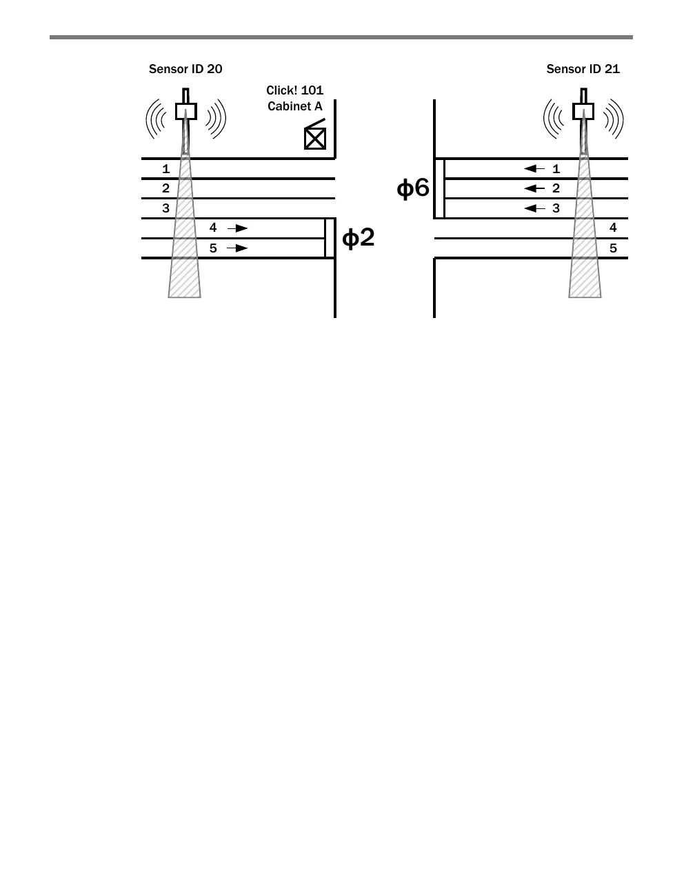
Figure 7.3 – The Click 101 Collects from Multiple Sensors
More sensors can be used to control all the phases at each intersection along an arterial or
within a city grid. Each sensor has two dierent buers for the lane-by-lane volume and
occupancy data. ere will be no loss of data on the sensor as long as each Click 101 com-
municates over a dierent serial port.
During its normal polling routine, the Click 101 can collect trac data from up to ten side-
re units. e normal polling routine will request new lane-by-lane volume and occupancy
data every time it cycles through the list of sensors. If a sensor does not respond aer ten
cycles, the Click 101 will suspend data queries to that sensor for one minute. Aer one min-
ute, the Click 101 will retry data queries twice. If those queries are unsuccessful, the Click
101 will suspend queries for another minute. is feature prevents unresponsive sensors
from unnecessarily slowing down the polling routine.
A Click 101 will not execute its normal polling routine if:
It is being programmed with Click Supervisor or the push-button.
It is being used for RS-232 to RS-485 conversion.
A device connected to the RS-485 bus has sent a passcode message to temporarily
suspend polling.
Lane outputs from any one of the side-re sensors can be mapped to any of the 16 digital
outputs. Mapping multiple lanes to a single output it also possible.
Physical Features
e Click 101 has 2 communication ports, 16 LEDs, 16 digital outputs and a push-button
(see Figure 7.4).