CHAPTER 4 CLICK 104 63
pre-wire the Click 104 before nal installation.
Rotary Switch
On the faceplate of the device is a rotary switch, numbered 0–9. is switch, which can be
twisted by inserting a small screwdriver into the arrow slot, is used to congure channels.
Mode Switch
e faceplate of the Click 104 features a push-button labeled Mode Switch, which is used to
cycle through and select menu and conguration options.
LEDs
e faceplate of the Click 104 has three banks of LEDs. e top bank is used for detection
indication, the second bank menu indication, and the third for menu indication as well as
operation states.
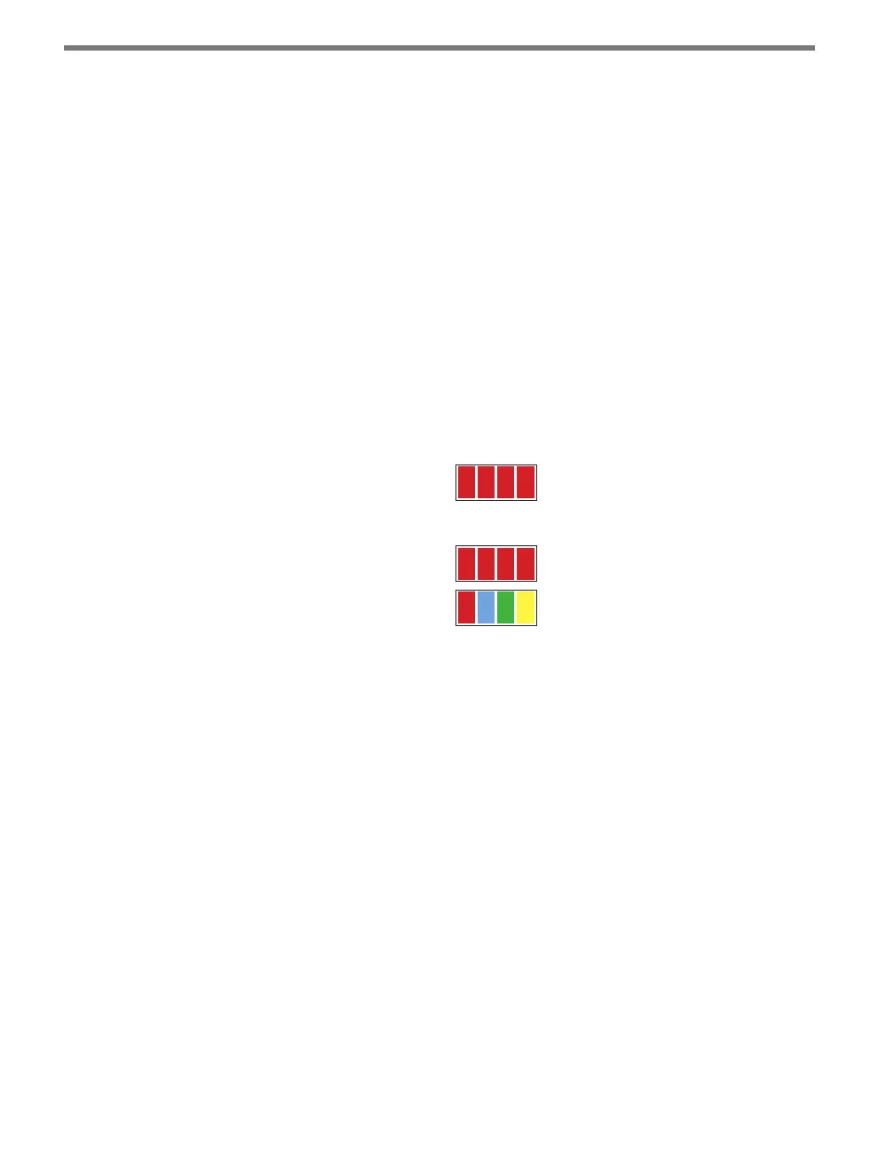
Menu
PWR OK TD RD
Channel
1 2 3 4
Figure 8.3 – Click 104 LEDs
e Channel LEDs are detection indicators; they consist of four red LEDs numbered 1–4,
each representing a channel (see Figure 8.3). An illuminated LED indicates that the asso-
ciated contact is being closed (this can mean either a vehicle detection or fail-safe mode,
which will be discussed later in this chapter). ese indicators are dedicated to detection
and have no other display purposes.
e menu indicator LEDs include two rows of LEDs (see Figure 8.3). e lower row con-
tains Level 1 indicators, while the upper row contains Level 2 indicators. Each level consists
of four LEDs numbered 1–4 (le to right). Level 1 LEDs (the multicolored row) display
which menu item is active. ese Level 1 LEDs are dual-purpose, each indicating both
menu selection as well as a normal operation state when not in Menu mode. e normal
operation state functions include:
Red (PWR) – Indicates the presence of power to the device.
Blue (OK) – Indicates proper system operation; it extinguishes during fail-safe mode.
Green (TD) – Indicates serial communication transmit data (from the Click 104) on
either bus 1 (data) or bus 2 (control).
Yellow (RD) – Indicates serial communication receive data (to the Click 104) on either