134 APPENDIX
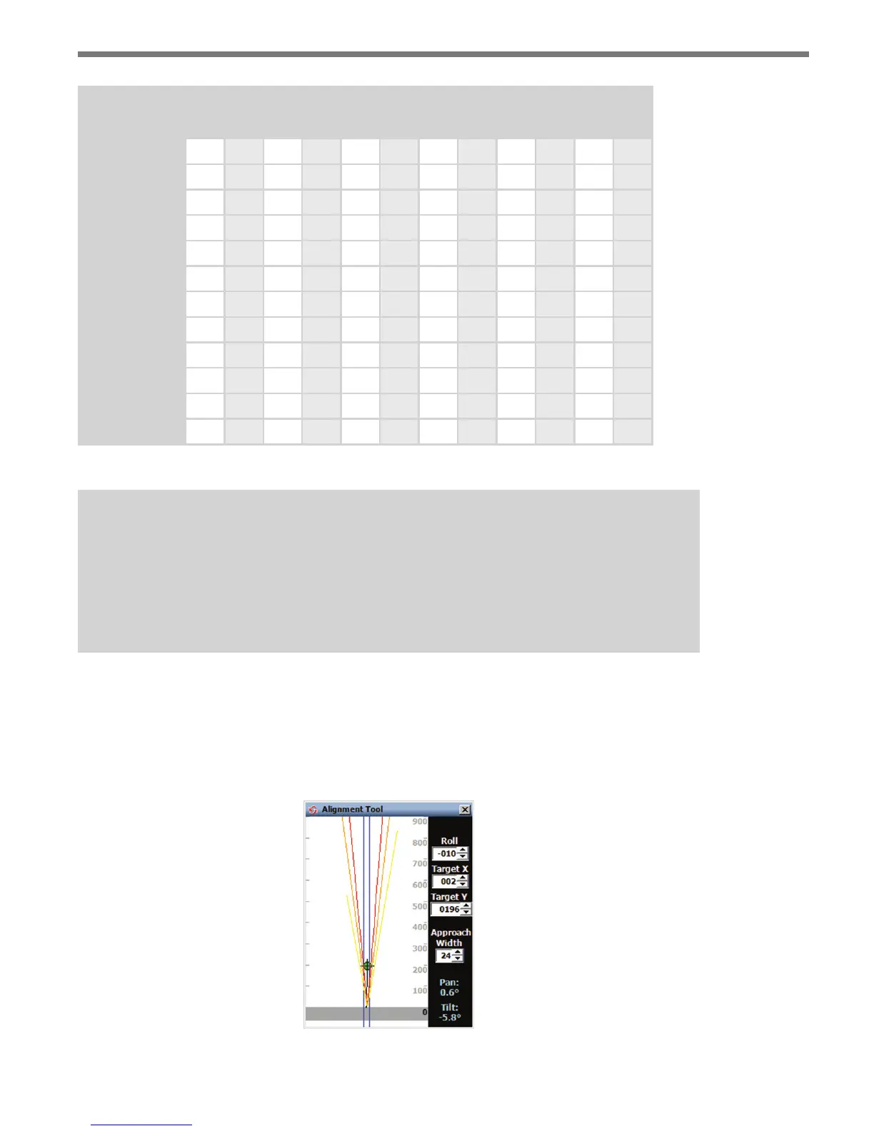
Height (ft/m)
Oset (ft / m)
17/5.2 20 /6.1 25/ 7.6 30/9.1 35/10.7 40 /12.2
Y Roll Y Roll Y Roll Y Roll Y Roll Y Roll
0/0 40 0° 45 0° 55 0° 60 0° 70 0° 75 0°
5 /1.5 45 19° 45 16° 60 13° 65 12° 70 10° 80 9°
10/3 50 35° 50 31° 60 25° 65 22° 75 19° 80 17°
15/4.6 50 47° 55 42° 65 36° 70 32° 75 28° 80 24°
20/6.1 55 56° 55 51° 65 44° 75 39° 80 35° 90 32°
25/ 7. 6 60 62° 65 57° 65 51° 75 46° 80 41° 90 38°
30/9.1 65 67° 70 63° 75 56° 80 51° 85 47° 95 43°
35/10.7 70 71° 75 67° 85 61° 85 56° 95 52° 95 48°
40/12.2 80 74° 90 71° 90 65° 95 60° 95 57° 100 52°
45/13.7 95 76° 100 73° 100 68° 100 64° 100 59° 105 56°
50/15.2 100 78° 100 76° 105 71° 110 66° 115 62° 120 59°
Table D.1 – Target Roll Angle
Note
If you would like to narrow the coverage of the sensor at far ranges, consider reducing
the target location by about 25%. For example, if your current target location is 40 ft,
you could reduce it to around 30 ft. Or, if you target location is 120 feet, you could re-
duce it to around 90 feet. This can be helpful if you have significant roadside clutter.
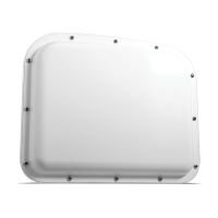
e information in this table was derived using the Alignment Tool in the conguration
software (see Figure D.1). You can use this tool to see the eects of a sensor that is not
properly aligned. e goal is to have the red contour (half power level contour) line up and
down the roadway over the lanes of interest. Chapter 8 of this document gives information
related to the use of the alignment tool.
Figure D.1 – Alignment Tool