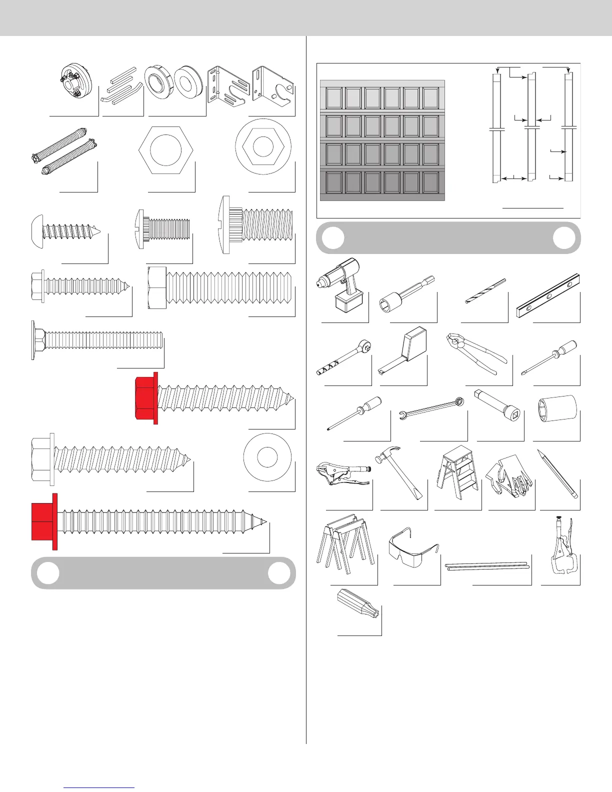
Center coupler
Keys
(as required)
Center bracket (as required)
Center bracket
bearing (as required)
1/4”- 20 Flanged
hex nuts (as required)
Torsion springs
RH/LH
3/8”- 16 Hex nuts
(as required)
3/8”-16 x 1-1/2” Hex bolts (as required)
1/4” - 14 x 1”
Lag screws (as required)
3/8”-16 x 3/4” Truss
head bolts (as required)
1/4”-20 x 9/16”
Track bolts (as required)
1/4” - 10 x 1”
Tamper-resistant
lag screw (as required)
1/4” - 20 x 1-7/8”
Carriage bolts (as required)
5/16” x 1-5/8” Hex head lag screws
5/16” x 1-5/8” Hex head lag screws
(as required)
Washer (as required)
5/16” x 2-1/2” Hex head lag screws
(RED HEAD) (as required)
Door Section Identification
When installing your door, you must use sections of the appropriate height in the right stack-
ing location. Determine, what sections you need to use in what order depends on the design
of your door.
Sections are stamped for identification, #1, #2, #3, #4, #5, #6, and #7. The stamp, located
on each side of the sections identifies the stacking sequence. The sequence is always
determined by #1 being the bottom section to #6 or #7 being the highest top section. If the
stamp on the section is illegible, refer to the section side view illustration. The section side
view illustration shows the section profile of all sections, and can also be used to identify
each section.
The BOTTOM SECTION can be identified by #1.
The INTERMEDIATE I SECTION can be identified by #2.
The INTERMEDIATE II SECTION can be identified by #3, for a 4 section high door only.
The INTERMEDIATE III SECTION can be identified by #4, for a 5 section high door only.
The INTERMEDIATE VI SECTION can be identified by #5, for a 6 section high door only.
The INTERMEDIATE V SECTION can be identified by #6, for a 7 section high door only.
The TOP SECTION can be identified by a #, being the highest section.
Bottom
rail
Bottom
rail
Typical
stamping
location
Top rail
Typical design option “Outside surface of
door sections shown”
Bottom
section
Intermediate(s)Top
section
Side views of sections
Outside
surface
Inside
surface
1.
Bottom
section
2.
Intermediate I
section
3.
Intermediate II
section
4. or 3.
Top
section
## 1
NOTE: 3 Section high doors do not have an
Intermediate II Section.
Tools Required
Power drill Socket driver: 7/16” Level
Drill bits: 1/8”, 3/16”,
9/32”, 7/16”, 1/2”
Ratchet wrench Tape measure Pliers / Wire cutters Flat tip screwdriver
r
Wrenches: 3/8”, 7/16”,
3” Ratchet
extension
Sockets: 7/16”,
1/2”, 9/16”, 5/8”
Vise clamps Hammer Step ladder PencilLeather gloves
Locking pliersSafety glasses
Approved winding bars
Saw horses
t
4