Please Do Not Return This Product To The Store. Call Us Directly! Our Trained Technicians Will Answer Your Questions and/or Ship Any Parts You May Need
You can reach us Toll Free at 1-888-827-3667 for Consumer Assistance or online at www.wayne-dalton.com
26
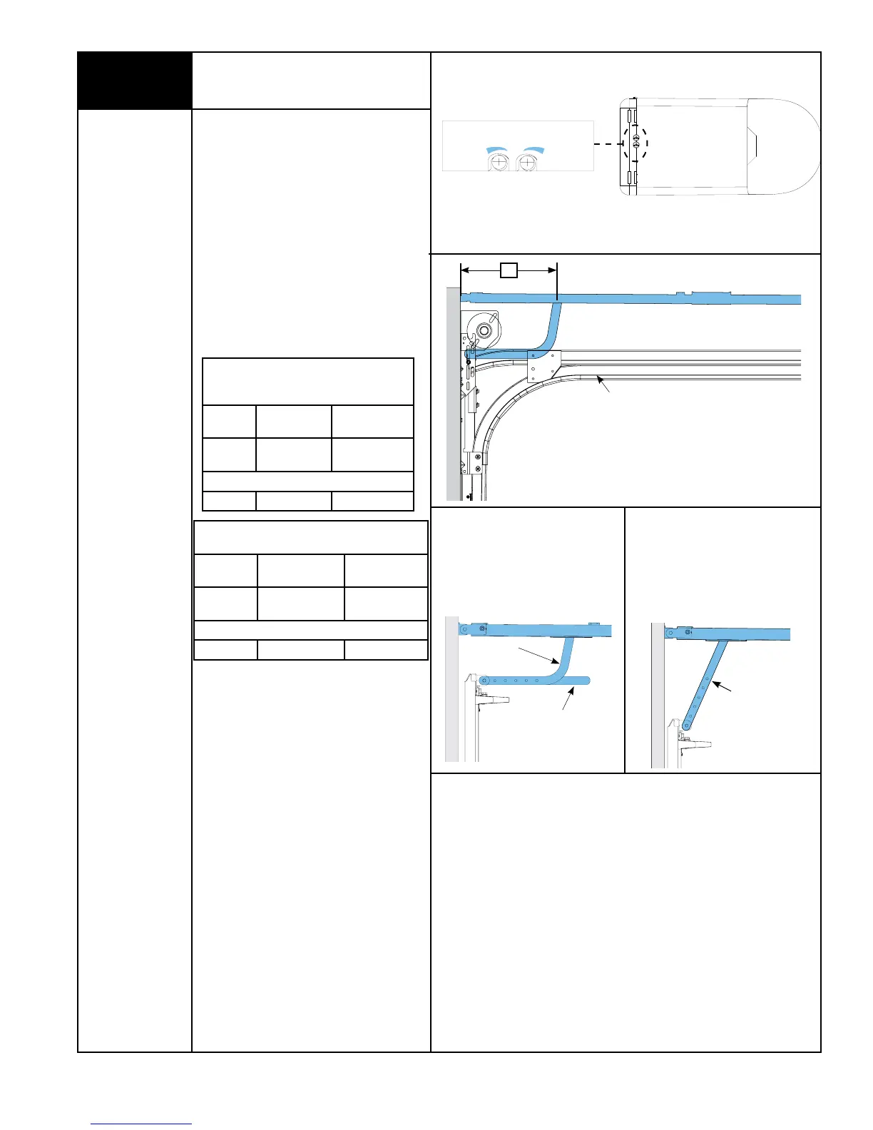
LOW HEADROOM:
Using the LOW HEADROOM TROLLEY
POSITIONING CHART, refer to DIM “X” to
set the distance from header to trolley, as
shown in FIG. 1.5.
NOTE: Depending on your setup, you may or
may not have to cut straight arm to
accomplish trolley settings.
If adjustment of the trolley position is
required, use the close travel adjustment
screw located on the bottom of the opener.
A 1/4 turn equals approximately 1” of trolley
travel; turn clockwise to decrease distance
DIM “X” and counter-clockwise to increase
distance DIM “X”.
NOTE: Proceed with “Connecting Door Arm
To Door” Step 21, on page 15.
LOW HEADROOM TROLLEY
POSITIONING CHART FOR (MODEL 9700)
DIM “X”
TYPE OF ARM
BEING USED
REFERENCE
ILLUSTRATIONS
15”-18”
CURVED /
STRAIGHT
FIG. 1.6
OPTIONAL HOOKUP
10” - 14” STRAIGHT FIG. 1.6a
FIG. 1.6
Curved Arm
Cut Straight Arm To
Accomplish Trolley
Setting
Low Headroom Track
“X”
FIG. 1.5
LOW HEADROOM TROLLEY
POSITIONING CHART FOR
(MODELS 9100, 9400, 9600, 5120 & 5140)
DIM “X”
TYPE OF ARM
BEING USED
REFERENCE
ILLUSTRATIONS
20”
CURVED /
STRAIGHT
FIG. 1.6
OPTIONAL HOOKUP
10” - 14” STRAIGHT FIG. 1.6a
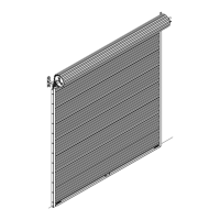
Setting Trolley Close Position/
Connecting Door Arm
(Continued)
OPEN
CLOSE
MORE
LESS
MORE
TRAVEL ADJUSTMENT
Bottom Of Opener
FIG. 1.4
FIG. 1.6a
Straight Arm