5
Note: Use these Notes of Installation, Use, and Maintenance in conjunction with the Drawings of Installation, Use, and Maintenance to perform the
installation. The following letters & numbers in parenthesis, [example: (A1)] cross reference items listed in each diagram of the Drawings of Installation,
Use, and Maintenance manual.
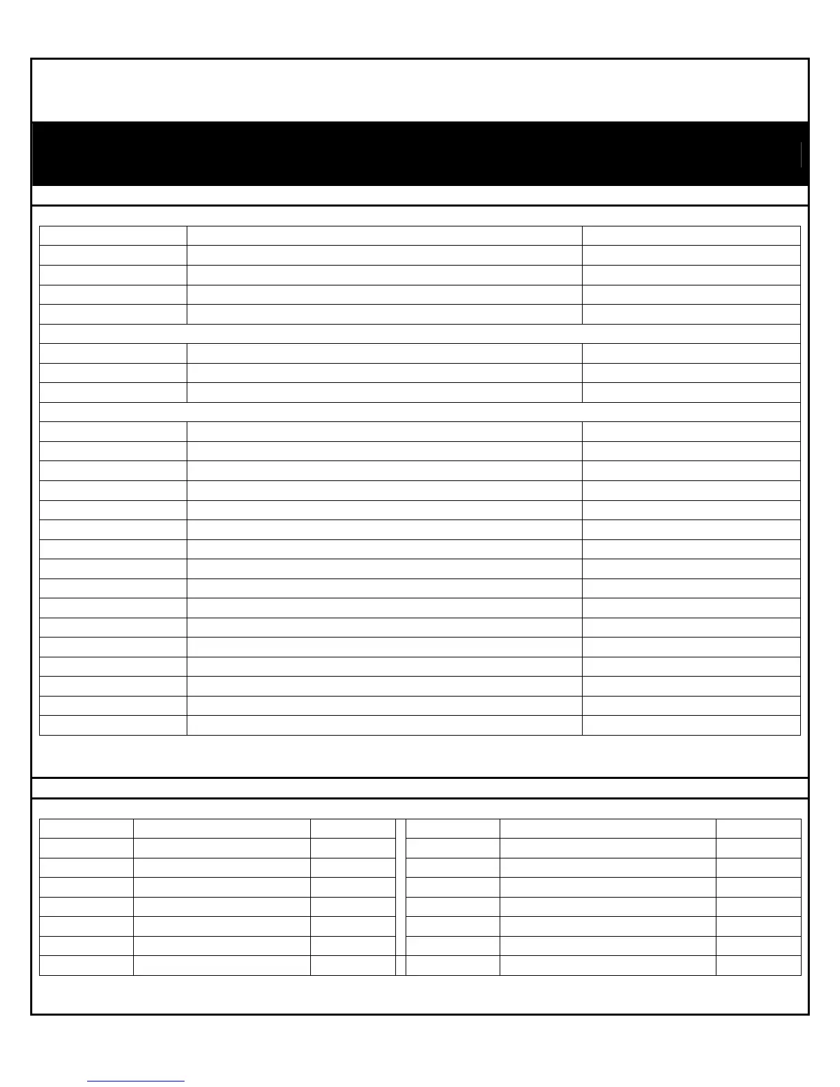
PACKAGE CONTENTS
PACKAGE CONTENTS “A” (SEE PAGE 2 OF DRAWINGS OF INSTALLATION, USE AND MAINTENANCE MANUAL)
CALL OUTS PARTS QUANTITY
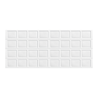
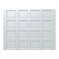
A1 Pre-assembled Door 1
A2 Horizontal Track 1 pair
A3 Entrapment Label 1
A4 Spreader Bar Assembly * 1
[*Attached to the bottom door section during packaging]
A4.1 Spreader Bar 1
A4.2 Slider Bars ** 2
A4.3 “L Bracket ** 2
[**Attached To Spreader Bar]
A5 “L” Bracket 2
A6 Ø 6 x 15 mm (1/4” - 20 x 9/16”) Track Bolt 10
A7 Ø 6 mm (1/4” – 20) Flange Hex Nut 10
A8 Ø 8 x 40 mm (5/16” x 1-5/8”) Lag Screw 13
A9 Molded Transition Track 1 Pair
A10 Anchors 13 (not supplied)
A11 Disconnect label 1
A12 Wall Station assembly : 1 (Supplied according to the model)
A12.1 Base 1
A12.2 Cover/Button assembly 1
A12.3 Circuit Board 1
A12.4 Phillips Head Screws 2
A12.5 Battery 1
A13 Remote Transmitter 1
A14 Wall Station reference label 1(Supplied according to the model)
A15 Light Fixture 1(Supplied according to the model)
TOOLS REQUIRED “B” (SEE PAGE 2 OF DRAWINGS OF INSTALLATION, USE AND MAINTENANCE MANUAL)
CALL OUTS PARTS QUANTITY CALL OUTS PARTS QUANTITY
B1 Electric Drill (With Clutch) 1 B8 Screw Driver (Flat Head) 1
B2 5 mm (3/16”) Drill Bit 1 B9 Step ladder 1
B3 Level 1 B10 Safety Glasses 1
B4 Ratchet Wrench 1 B11 Gloves 1
B5 75 mm (3”) extension 1 B12 11 mm (7/16”) Hex Head Driver 1
B6 11 mm (7/16”) Wrench 1
B13 Screw Driver (Phillips Head) 1
B7 Tape measure 1