37
OIL PIPE SIZING INFORMATION
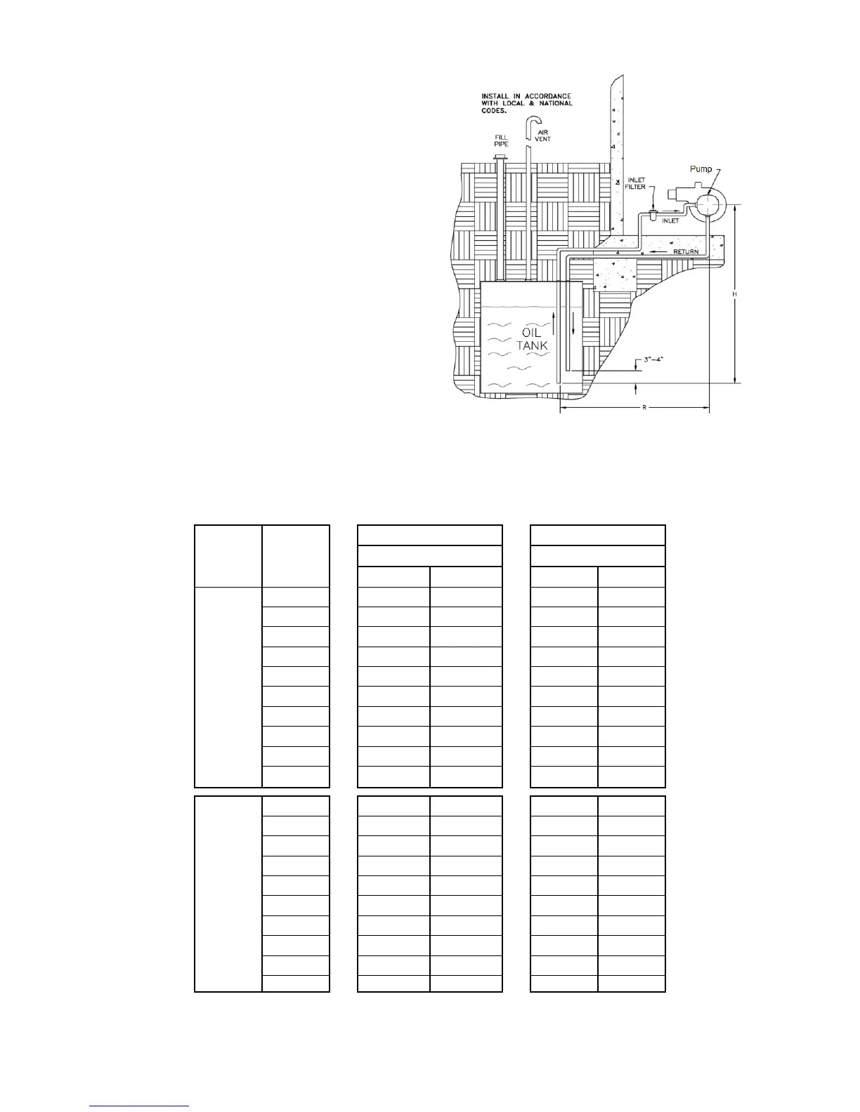
Figure 27– Fuel line sizing diagram for fuel tank below burner, burner setup in two-pipe
operation
Table 5: Max Allowable Fuel Line Lengths for two pipe operation
NOTE: Max. total line length L=H + R, values were calculated based off a fuel viscosity of 57 SSU. Elbows, valves & filters
will further reduce total line length. It is recommended to avoid 3/8” lines where feasible.
L= Max total line length (ft.), H+R
H= Vertical distance in feet from bottom of
tank to centerline of pump, or lift (ft.)
R= Horizontal distance in feet from
tank to centerline of burner pump (ft.)
Q=firing rate capacity of fuel pump (gal/hr)