FLAME
SENSING
The Honeywell
S89 series
primary
ignition controls
utilize the
flame
current rectification
principal
for main
burner
flame
sensing.
The
flame
rectification
phenomenon
occurs
as follows.
The ignited
gas
flame causes the
immediate
atmosphere around the flame to become
ionized
(gas
atoms become electrically charged). The
ionization
causes the atmosphere around the
flame to become
electrically conductive. An AC
voltage
output
from
the
control sensing
circuit is routed through the flame
sensor
probe.
When the
sensor
probe
and
the burner
head
are
both in contact with
a
properly
adjusted
flame,
the burner
head with its
larger surface attracts
more free
electrons, thus becoming negatively charged.
The
sensor
probe
with its
small surface area
gives
up free
electrons, thus becoming
positively
charged.
The free
electrons
from
the
AC voltage
in the
sensor
probe
flow
PROBE
DIM
IGNITER
't
5/8
41.2Emm
SENSOR1 1/4
J1.75mm)
through the
ionized
gas
flame to the
grounded
burner
head. As the AC current
passes
through the
gas
flame,
it is rectified into a DC current flowing back to the
grounded
side
of the sensing circuit.
The flame in
actuality is a
switch.
When
the
flame is
present,
the
switch
is
closed
allowing current to flow through the
sensing
circuit of the control.
When
no
flame is
present,
the
switch
is
open
with no current
flowing
through the
sensing circuit of
the
control.
The DC
current
flow is measured in units called
DC
microamperers. A steady DC
microamp
current of
.8
minimum
(and
steady) or higher through the sensing
circuit of the
primary
ignition control is
sufficient
to keep
the burner
running without
a safety
lockout.
See
Figure
13 for
sensor
probe
and electrode dimensional settings,
Figure 14 for flame current measurement.
13/16 Q0,64nn)
REF,
F-3t+
|
{ls.0smm)
(2,381mn)
1
/
16
(1.588mm)
Figure 13
S89
FLAME CURRENT
MEASUREMENT
Figure 14
FLAME SENSOR
CURRENT
CHECK-USE
pA
SCALE
TO
SENSOR
MULTIPURPOSE
METER
DISCONNECT
WIRE FFOM
SENSE
TEBMINAL
RED(+
BLACK(-)
0.8
uA
DC
MINMUM
(AND
STEADY)
O
\'C
PAGE 11
FLAME SENSING
The Honeywell S89 series primary ignition controls
utilize the flame current rectification principal for main
burner flame sensing.
The flame rectification phenomenon occurs as follows.
The ignited gas flame causes the immediate
atmosphere around the flame to become ionized (gas
atoms become electrically charged). The ionization
causes the atmosphere around the flame to become
electrically conductive.
An
AC
voltage output from the
control sensing circuit is routed through the flame
sensor probe. When the sensor probe and the burner
head are both
in
contact with a properly adjusted flame,
the burner head with its larger surface attracts more free
electrons, thus becoming negatively charged. The
sensor probe with its small surface area gives
up
free
electrons, thus becoming positively charged. The free
electrons from the
AC
voltage
in
the sensor probe flow
through the ionized gas flame to the grounded burner
head.
As
the
AC
current passes through the gas flame,
it
is
rectified into a
DC
current flowing back
to
the
grounded side of the sensing circuit. The flame in
actuality
is
a switch. When the flame
is
present, the
switch
is
closed allowing current
to
flow through the
sensing circuit of the control. When no flame is present,
the switch
is
open with
no
current flowing through the
sensing circuit of the control.
The
DC
current flow is measured
in
units called
DC
microamperers. A steady
DC
microamp current of
.8
minimum (and steady) or higher through the sensing
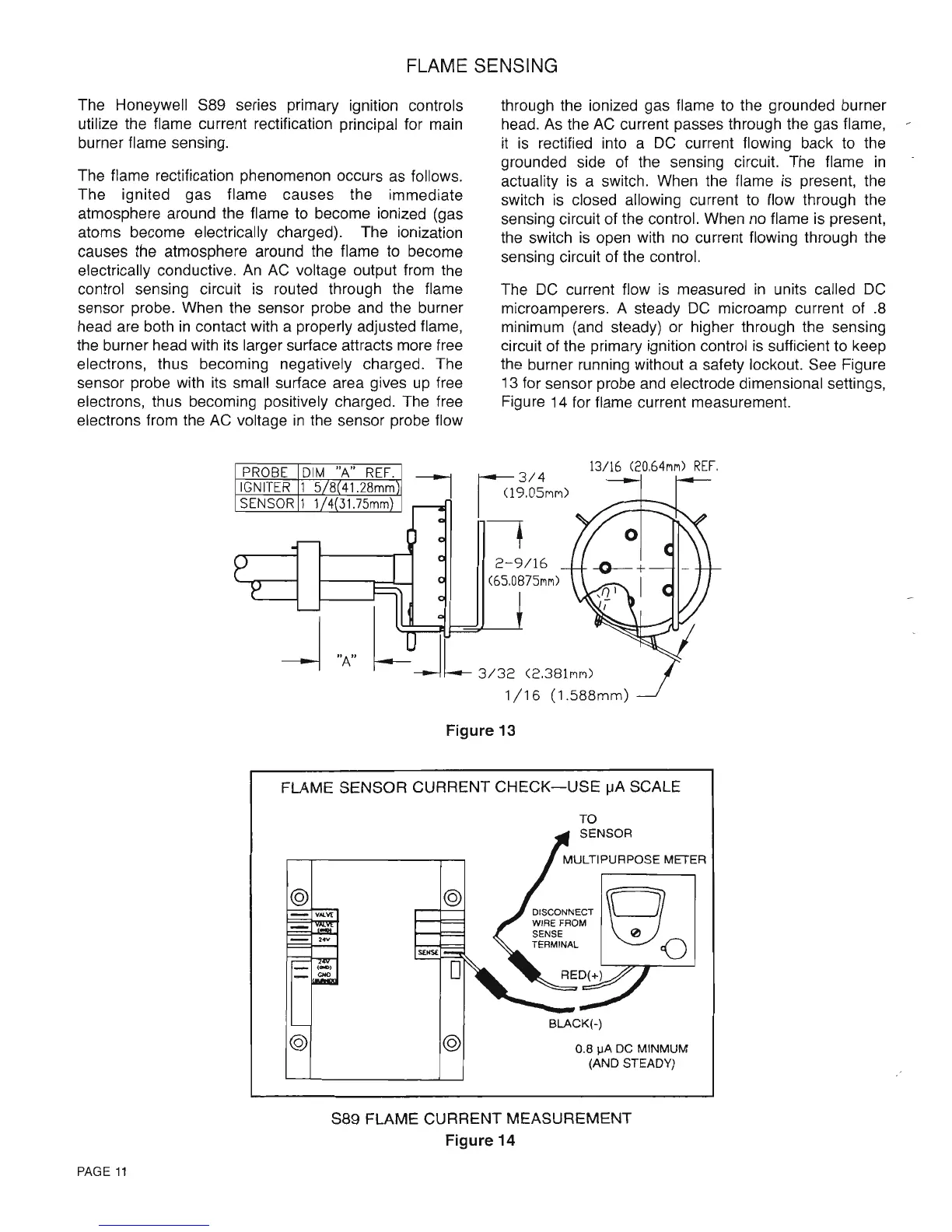
circuit of the primary ignition control
is
sufficient to keep
the burner running without a safety lockout. See Figure
13 for sensor probe and electrode dimensional settings,
Figure 14 for flame current measurement.
"A"
13/16
(20,64MM)
REF.
~3/4
I <l9,05MM)
-,
Figure 13
FLAME SENSOR CURRENT
CHECK-USE
jJA
SCALE
@
_ VAlVE
- 24V
-
(~)
_
GHO
@
@
@
TO
SENSOR
BLACK(-)
0.8
~A
DC
MINMUM
(AND STEADY)
S89 FLAME CURRENT MEASUREMENT
Figure 14
PAGE
11
 Loading...


