Network Video Recorder(NVR)
User Manual
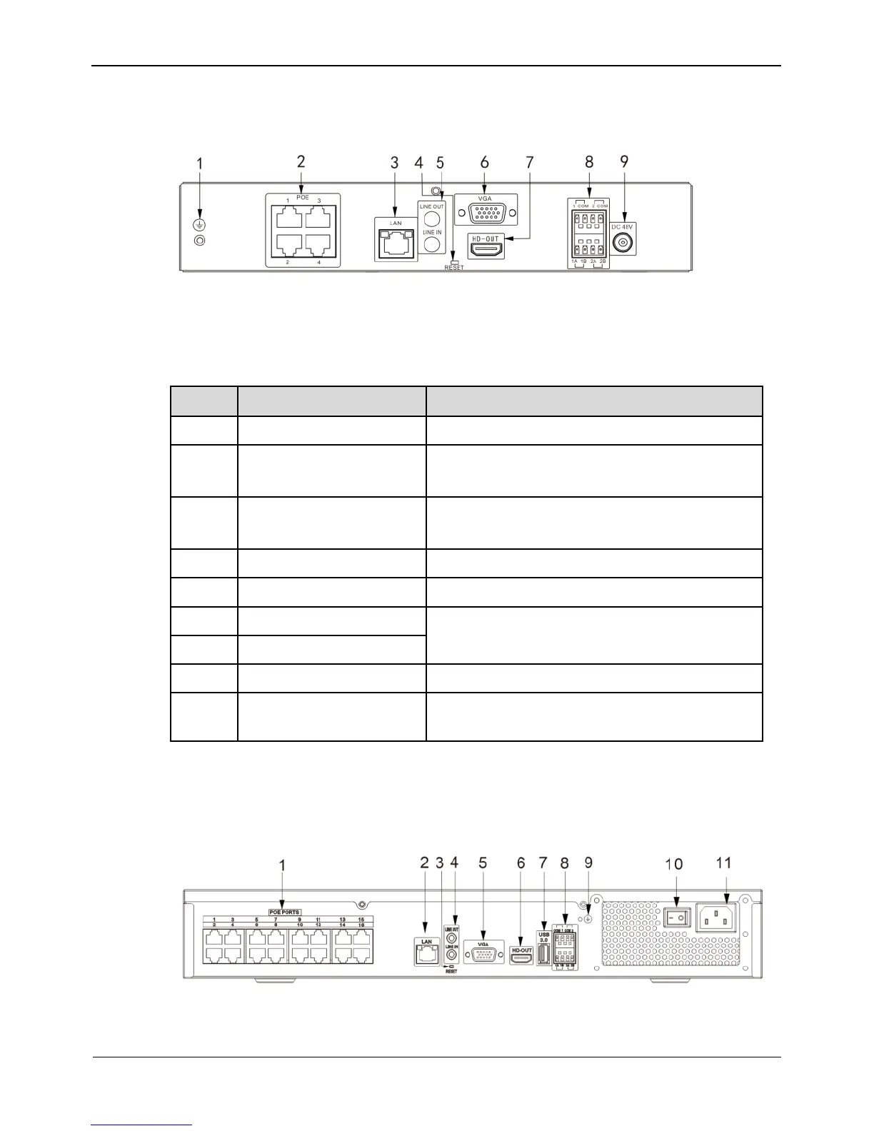
Figure 3-3 shows the rear panel of 0E-4CHNVR1TB & 0E-4CHNVR2TB and the
interfaces on it.
Figure 3-3 Rear panel of 0E-4CHNVR1TB & 0E-4CHNVR2TB
Table 3-2 shows the description of rear panel of 0E-8CHNVR2TB, 0E-4CHNVR1TB
& 0E-4CHNVR2TB.
Table 3-2 Elements of the real panel
Safe ground screw of the device
RJ45 10 /100/1000 Mbps adaptive
Ethernet interface
Audio input/ Audio output
2 alarm input, 2 alarm output
AC 110V/220V power input interface of the
device
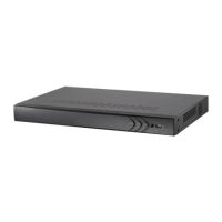
Figure 3-3 shows the rear panel of 0E-16CHNVR2T & 0E-16CHNVR4T and the
interfaces on it.
Table 3-3shows the description of rear panel of 0E-16CHNVR2T & 0E-16CHNVR4T.