Do you have a question about the WBOX Technologies WBXRN080P8E and is the answer not in the manual?
Subject to the terms and conditions of this Limited Warranty, from the date of sale by ADI to the Buyer through the period of time for product categories specified in Section 1(b), ADI warrants its W Box Technologies products to be free from defects in materials and workmanship under normal use and service, normal wear and tear excepted.
Specific Warranties for product categories are as follows:
THERE ARE NO WARRANTIES OR CONDITIONS, EXPRESS OR IMPLIED, OF MERCHANTABILITY, OR FITNESS FOR A PARTICULAR PURPOSE OR OTHERWISE, WHICH EXTEND BEYOND THE DESCRIPTION ON THE FACE HEREOF.
Buyer agrees to limit liability to its customers to the fullest extent permitted by law. Buyer acknowledges that ADI shall only be deemed to give consumers of its products such statutory warranties as may be required by law.
Subject to the terms and conditions listed below, during the applicable warranty period, ADI will replace Product or provide a credit at purchase at its sole option free of charge any defective products returned prepaid.
This equipment has been tested and found to comply with the limits for a digital device, pursuant to part 15 of the FCC Rules. These limits are designed to provide reasonable protection against harmful interference when the equipment is operated in a commercial environment.
This product and - if applicable - the supplied accessories too are marked with "CE" and comply therefore with the applicable harmonized European standards listed under the Low Voltage Directive 2006/95/EC, the EMC Directive 2004/108/EC, the RoHS Directive 2011/65/EU.
Ensure unit is installed in a well-ventilated, dust-free environment. Unit is designed for indoor use only. Keep all liquids away from the device. Ensure environmental conditions meet factory specifications.
Improper use or replacement of the battery may result in hazard of explosion. Replace with the same or equivalent type only. Dispose of used batteries according to the instructions provided by the battery manufacturer.
Windows and Windows mark are trademarks or registered trademarks of Microsoft Corporation in the United States and/or other countries.
VGA is the trademark of IBM. UPnP™ is a certification mark of the UPnP™ Implementers Corporation.
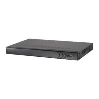
Power indicator turns yellow when system is running. Status indicator blinks red when data is being read from or written to HDD. Tx/Rx indictor blinks yellow when network connection is functioning properly.
Power Supply: 48V DC power supply for 4ch NVR and AC 100~240V for 8ch &16ch NVR. Audio In: RCA connector for audio input. HDMI Interface: HDMI video output connector.
The default user name is admin and password is wbox123. You must change these default credentials to protect against unauthorized access to the product.
Proper startup and shutdown procedures are crucial to expanding the life of the NVR. Before you start: Check that the voltage of the extra power supply is the same with the NVR's requirement.
After entering the local operation interface of the device, you can right click on the screen to access the right-click menu and select the Menu to enter the menu of the device.
Live view shows you the video image getting from each camera in real time. The NVR will automatically enter Live View mode when powered on.
In the live view mode, there are icons at the right top of the screen for each channel, showing the status of the record and alarm in the channel.
In live view mode, there are many functions provided. The functions are listed below. Single Screen: showing only one screen on the monitor. Multi-screen: showing multiple screens on the monitor simultaneously.
Live View settings can be customized according to different needs. You can configure the output interface, dwell time for screen to be shown, mute or turning on the audio, the screen number for each channel, etc.
Video Output Interface: Designates the output to configure the settings for. Outputs include HDMI/VGA and CVBS (depends on the model). Live View Mode: Designates the display mode to be used for Live View.
Select an output interface and select a screen layout. Click to select a screen in the right region and double-click to select a channel in the left region. Thus the selected channel will be displayed in the corresponding screen.
After logging out, the monitor turns to the live view mode and if you want to do some operation, you need to enter user name and password to log in again.
Ensure the network connection is valid and correct.
Right-click the mouse when you in the live view mode to show the right-click menu.
The online cameras with same network segment will be displayed in the camera list. Click the button to add the camera.
Click the Custom Adding button to pop up the Add IP Camera (Custom) interface.
Enter the Camera Management interface. Menu> Camera> Camera
Make sure that the HDD has already been installed. If not, please install a HDD and initialize it. You may refer to the user manual for detailed information.
Click Remote Configuration> Camera Settings> Record Schedule to enter Record Schedule settings interface.
Configure All Day or Customize Record: If you want to configure the all-day recording, please check the All Day checkbox. If you want to record in different time sections, check the Customize checkbox.
Select a Record Type. The record type can be Continuous, Motion, Alarm, Motion & Alarm, Motion | Alarm and VCA.
Play back the recorded video files of a specific channel in the live view mode. Channel switch is supported.
Choose a channel in live view mode using the mouse and click the button in the quick setting toolbar.
Enter the Playback interface. Mouse: right click a channel in live view mode and select Playback from the menu.
The toolbar in the bottom part of Playback interface can be used to control playing progress, as shown below.
Enter Video Export interface. Choose the channel(s) you want to back up and click the Quick Export button.
Enter Export interface, choose backup device and click the Export button to start exporting.
The record files can be backup to various devices, such as USB devices (USB flash drives, USB HDDs, USB writer) and SATA writer.
Click Export All button to export all the recording files. Or you can select recording files you want to back up, and click Export button to enter Export interface.
If the inserted USB device is not recognized: Click the Refresh button. Reconnect device. Check for compatibility from vendor.
Open web browser, input the IP address of the device and then press Enter. The login interface appears.
The default IP address is 192.0.0.64. The default user name is admin and password is wbox123.
After the installation, you can configure and manage the device remotely.
WBXRN040P4E: 4-ch. WBXRN080P8E: 8-ch. WBXRN160P8E: 16-ch. Incoming bandwidth: 40Mbps/80Mbps. Outgoing bandwidth: 80Mbps.
HDMI/VGA output: 1-ch, resolution: 1920 x 1080/60Hz, 1600 x 1200/60Hz, 1280 x 1024/60Hz, 1280 x 720/60Hz, 1024 x 768/60Hz. Live view / Playback resolution: 5MP/3MP/1080P/UXGA/720P/VGA/4CIF/DCIF/2CIF/CIF/QCIF.
Hard disk: 1 SATA interface for 1 HDD / 2 SATA interfaces for 2 HDDs. Capacity: Up to 4TB for each disk. Power supply: 48V DC / 100~240V AC.
| Brand | WBOX Technologies |
|---|---|
| Model | WBXRN080P8E |
| Category | DVR |
| Language | English |