DVS/GSE GSE DVS Field Service Manual
09030-78B 40 of 49
Webasto Charging Systems, Inc.
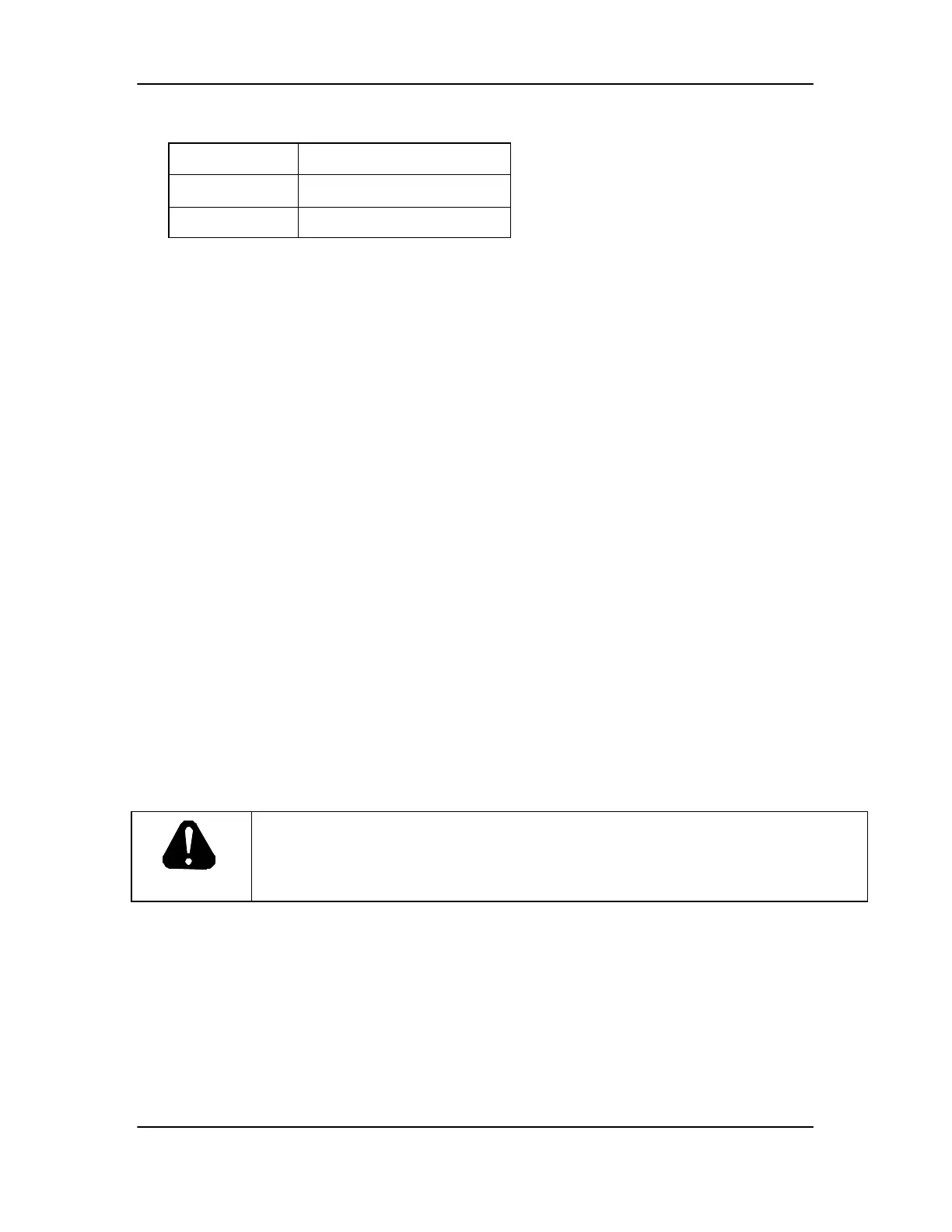
Table 5. Transformer T3 Expected Voltages
Test Across Expected Voltage (VAC)
H1-H4 480
X1-X3 120
If H1-H4 voltage is less than 440VAC, turn off power at utility disconnect and check all electrical
connections between utility disconnect and transformer T3. If proper voltage is measured across
H1-H4, but voltage across X1-X3 deviates from expected voltage by more than 12VAC, turn off
power at utility disconnect and check all connections into transformer T3. If all connections are
correct, look for signs of overheating or other damage in wiring and components downstream of
transformer T2 (relays K2 and K3, yellow and red lights, rectifiers D2 and D3, terminal blocks
TB1 and TB3, etc.). If components do not appear to be damaged, replace transformer T3 and re-
test. If problem persists, check 120VAC wiring between Power Supply cabinet and PowerStation
cabinet.
3.4.8 Troubleshooting Thermal Issues
Turn off power to the DVS at the utility disconnect. Lock and tag disconnect. The DVS contains
six thermal switches, located as shown on Figure 3
Check switches S1-S5 to see if any have tripped. Also check for any visible signs of damage. If
any switches are damaged, replace as follows:
1. Remove fast-on connectors and fasteners
2. Lift out to remove
3. Install new switch by reversing steps above (NOTE: Replace heatsink compound
P/N 04067 as needed).
Otherwise, if a switch has tripped, the red button in the center of the switch will have popped out
further than an untripped switch. Reset any tripped switches by pushing red button in. Check all
Power Supply cabinet wiring and components for signs of overheating or other damage. Check
all Power Supply cabinet connectors for damage or improper assembly. Check all fasteners and
tighten if necessary. Check operation of main contactor per section 3.4.5 to make sure it has not
failed in the closed position.
DANGER
USE EXTREME CAUTION WHEN TROUBLESHOOTING THE DVS WITH
ANY PANEL REMOVED. ELECTRIC SHOCK CAN KILL: Touching live
electrical parts can cause fatal shocks or severe burns. The input power circuitry and
internal circuits are live whenever input power is on.
Turn on power at utility disconnect. Check line-to-line voltage per section 3.4.3. Verify
operation of fans, Fan1 and Fan2 by turning off the unit, clipping the jumper cable across the
leads on thermal switch, S6, then turning the unit back on. If fans do turn on when jumper wire is
in place, turn unit off, replace thermal switch S6 and remove jumper wire, and turn unit back on.
Confirm that fans are now functioning properly.
If one or both fans do not turn on, check all wiring connecting fans to transformer. If wiring and
connections appear to be correct, replace the non-functioning fan(s) as follows:
• Remove the two screws connecting the fan backing plate to the rear panel. See Figure 9
for detail.