DVS/GSE GSE DVS Field Service Manual
09030-78B 45 of 49
Webasto Charging Systems, Inc.
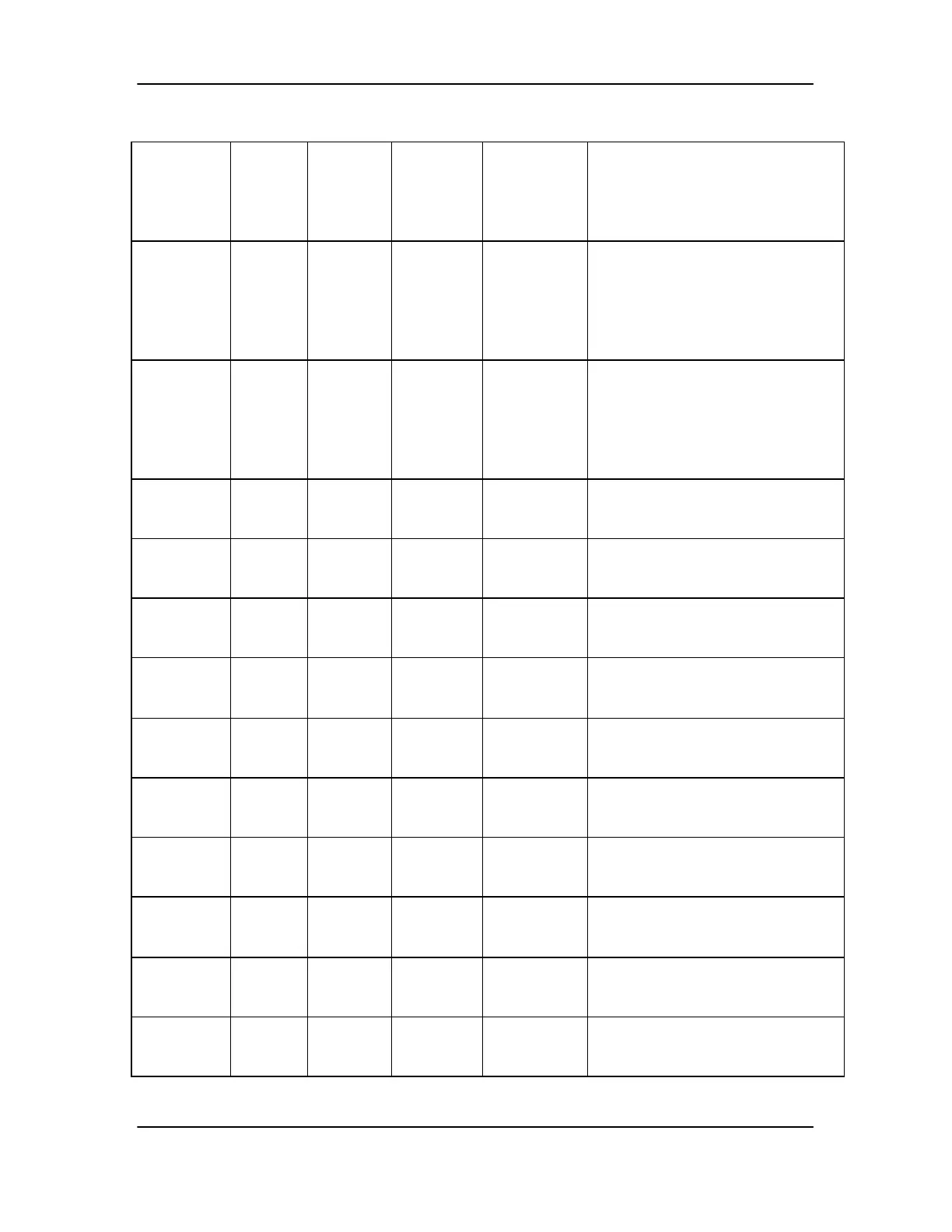
Table 6. Relay System Test Points and Expected Values
System
Component
First
Test
Point or
Pin
Number
Second
Test
Point or
Pin
Number
Expected
Value,
System
Off
Expected
Value,
System On
Comments/ Actions
TB1 1 2 Open 100-
135VAC
while
booting/
Short when
enabled
If test fails, troubleshoot
PowerStation Cabinet per section
3.1
TB1 3 4 Open 100-
135VAC
while
booting/
Short when
enabled
If test fails, troubleshoot
PowerStation Cabinet per section
3.1
K2 A1(13) A2(14) 0VAC 115-
125VAC
If test fails, check T2 per section
3.4.8 and troubleshoot thermal
system per section 3.4.8
K2 41(12) 42(4) Closed Open If test fails, and K2, A1-A2 shows
proper voltage, replace relay
assembly
K2 41(12) 44(8) Open Closed If test fails, and K2, A1-A2 shows
proper voltage, replace relay
assembly
K2 11(9) 12(1) Closed Open If test fails, and K2, A1-A2 shows
proper voltage, replace relay
assembly
K2 11(9) 14(5) Open Closed If test fails, and K2, A1-A2 shows
proper voltage, replace relay
assembly
K3 A1(13) A2(14) 0VAC 115-
125VAC
If test fails, check T2 per section
3.4.8 and troubleshoot thermal
system per section 3.4.8
K3 41(12) 42(4) Closed Open If test fails, and K3, A1-A2 shows
proper voltage, replace relay
assembly
K3 41(12) 44(8) Open Closed If test fails, and K3, A1-A2 shows
proper voltage, replace relay
assembly
K3 11(9) 12(1) Closed Open If test fails, and K3, A1-A2 shows
proper voltage, replace relay
assembly
K3 11(9) 14(5) Open Closed If test fails, and K3, A1-A2 shows
proper voltage, replace relay
assembly