DVS/GSE GSE DVS Field Service Manual
09030-78B 30 of 49
Webasto Charging Systems, Inc.
3.1.4.10 Display Board (P/N 06457)
The Display board is mounted to the door underneath the Control board (Ref. 3.1.4.9). It is held
in place by 4 5/16
th
nuts. A 14 pin connector connects the Display board to the Control board.
To remove:
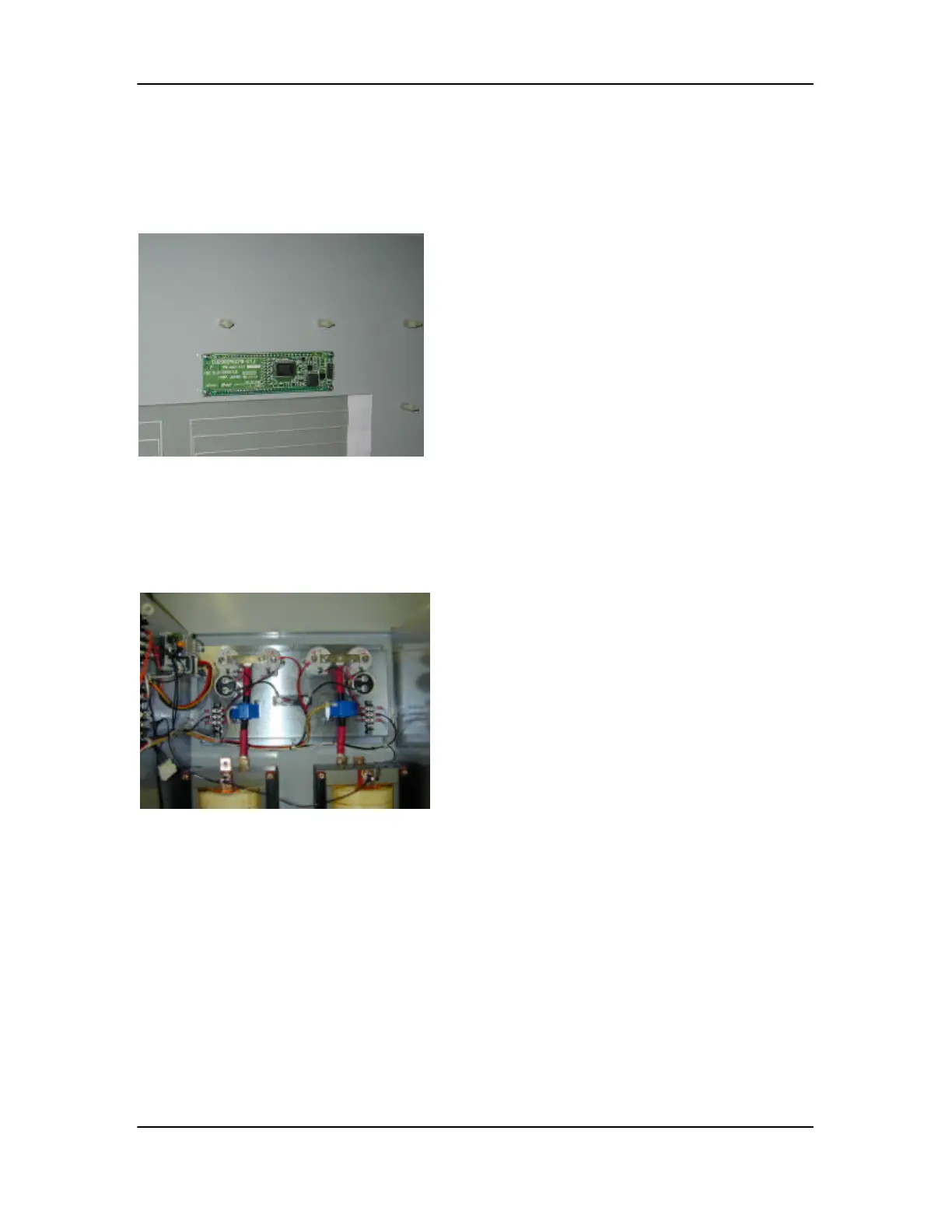
3.1.4.11 Current Sensors (P/N 05109)
The Current Sensors are mounted on the back wall of the station. They are held in place by 2
phillips head screws. A 2/0 cable runs through the sensors from the inductor to the buss bar
between the contactors. To remove:
2. Remove the 4 5/16
th
nuts (Be careful not
to damage the components while
loosening or tightening the nuts)
3. Remove the board
4. Reverse these steps to install the board
Remove the 7/16th nut that mounts the
2/0 cable to the buss bar between the
contactors.
2. Remove the 2 phillips head screws
3. Slide the Current Sensor over the lug to
remove
4. Reverse these steps to install the sensor

 Loading...


