DVS/GSE GSE DVS Field Service Manual
09030-78B 28 of 49
Webasto Charging Systems, Inc.
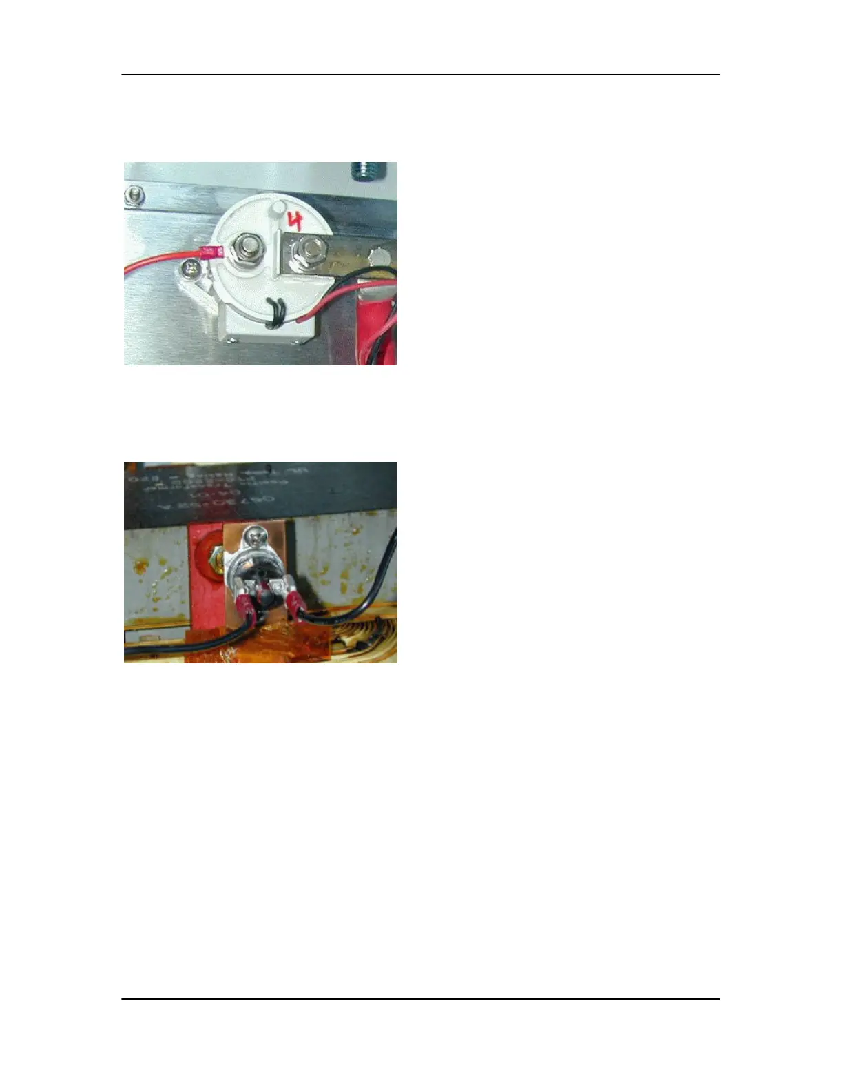
3.1.4.7 Contactor (P/N 06902)
3.1.4.8 Inductor Thermal Switches (P/N 05162)
This item can be found on the copper tabs
protruding from the tops of the inductors.
1. Unplug the faston connections
2. Remove the mounting screws and remove
switch.
3. Reverse these steps to install new switch,
adding heatsink compound if needed (there
should be a thin film).
Four of these contactors are mounted to the
back wall of the PowerStation cabinet, near the
top.
1. Remove the power cable, bus bar, and
unplug the red and black coil leads.
2. Remove the 2 mounting screws.
3. Install the new contactor
4. Connect power cable, bus bar and coil
leads.