Do you have a question about the Weber E-320 and is the answer not in the manual?
Lists necessary tools and identifies all components for grill assembly with corresponding part numbers.
Detailed instructions for attaching frame parts, including wheel placement and securing bottom rack.
Guidance on installing side panels, likely involving specific fasteners or alignment.
Instructions for connecting rear and bottom panels to the main structure.
Ensures all main structure bolts are correctly installed and tightened using provided or specific tools.
Confirms bottom rack is locked and details further wheel assembly or attachment.
Instructions for assembling and attaching components related to the side burner unit.
Guidance on fitting and securing the main control panel to the grill body.
Details for installing drip pans, handle hardware, and potentially related bracketry.
Focuses on connecting the side burner tube and attaching side panels with correct alignment.
Covers installation of cooking grates, warming racks, Flavorizer bars, and decorative trim pieces.
| Lid | Yes |
|---|---|
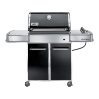
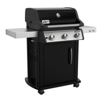
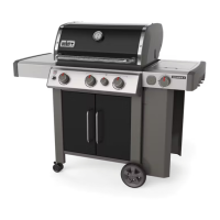
| Form factor | Cart |
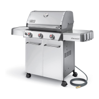
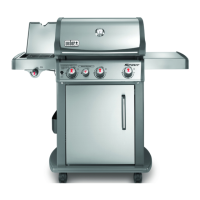
| Product color | Black, Stainless steel |
| Housing material | Stainless steel |
| Built-in capability | - |
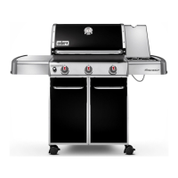
| Cooking surface shape | Rectangular |
| Cooking surface (W x D) | 620 x 450 mm |
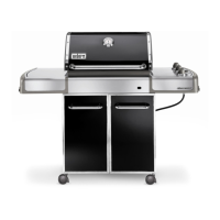
| Type | Barbecue |
| Heat source | Gas |
| Total power | - W |
| Number of cooking zones | 3 zone(s) |
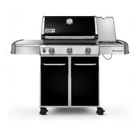
| Depth | 812 mm |
|---|---|
| Width | 1320 mm |
| Height | 1600 mm |