Appendix: Using the I/O connector
Using the 12 pin I/O cable, you can connect to a digital tachograph, as well as use
configurable digital inputs and outputs to connect accessories and 3rd-party devices.
For example, you can record inputs, for keeping a digital logbook with the help of a
switch, reporting times the vehicle is idling etc. You can connect the 12 pin I/O cable
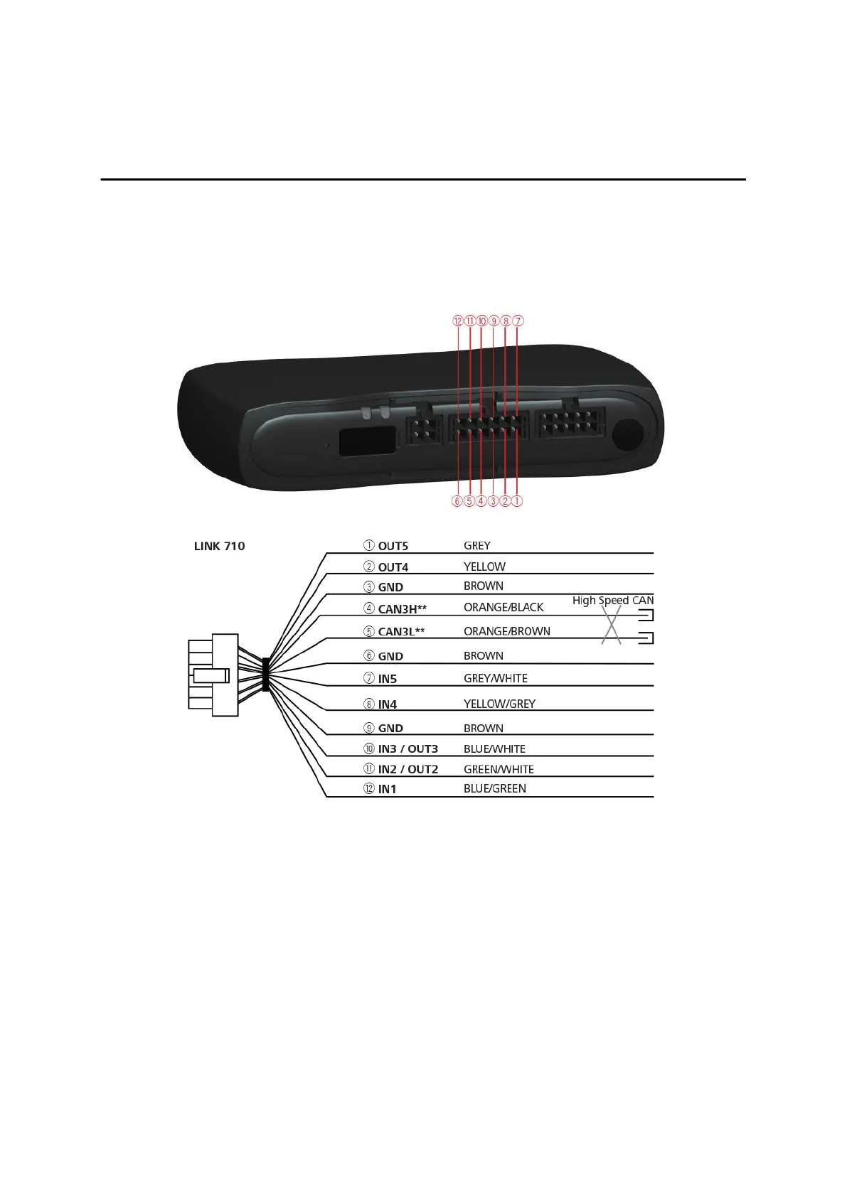
from Webfleet Solutions to the 12 pin I/O cable connector of the LINK 710.
** Twisted pair. Loose ends of CAN L/CAN H wires must be protected against short
circuits. Separate by using a heat shrink tube.
Wiring digital inputs
The digital inputs of the LINK 710 operate according to the principle of a voltage
detector. Voltages below 2 Volts are definitively interpreted as being low and voltages
higher than 3 Volts are definitively interpreted as being high. The maximum
permissible input voltage is 30 Volts. Low/high switching (increasing input voltage)
typically occurs at 2.8 Volts. High/low switching (decreasing input voltage) typically
occurs at 2.1 Volts. The hysteresis of 0.7 Volts is to avoid rapid switching.
Interference voltages at the digital inputs must remain below 2 Volts. In order to
guarantee this, the input wire of the connecting cable should never remain
unconnected. If a digital input is not being used, the input wire must be connected to
ground (GND). To evaluate a switch, this switch needs to be designed as a change-
27