Do you have a question about the weBoost Drive Reach and is the answer not in the manual?
Indicates the booster is functioning properly with no installation issues.
Indicates reduced power due to minor oscillation; a safety feature.
Indicates major oscillation (feedback loop); a safety feature shutting off a band.
Indicates no power. Verify the power supply for the Signal Booster.
Steps to resolve red or blinking red booster lights and improve signal.
Answers to common questions about booster operation and signal interference.
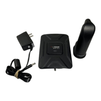
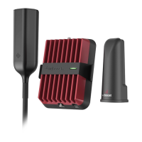
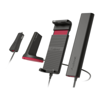
Details of certified outside antenna kits, including part numbers and cable types.
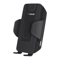
Details of certified inside antenna kits, including part numbers and cable types.
| Max Gain | 50 dB |
|---|---|
| Impedance | 50 Ohms |
| Connectors | SMA Female |
| Gain | 50 dB |
| Uplink Frequency Ranges | 698-716 MHz, 776-787 MHz, 824-849 MHz, 1710-1755 MHz, 1850-1915 MHz |
| Downlink Frequency Ranges | 728-746 MHz, 746-757 MHz, 869-894 MHz, 1930-1995 MHz, 2110-2155 MHz |
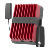
| Power | 12V DC |
| Dimensions (Amplifier) | 6 x 4.5 x 1.5 in |