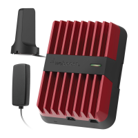
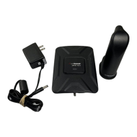
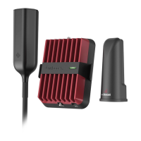
DRIVE REACH VEHICLE SIGNAL BOOSTER
9
FREQUENTLY ASKED QUESTIONS
How can I contact customer support?
Customer Support can be reached Monday thru Friday by calling
Why do I need to create distance between the booster and the antenna?
Antennas connected to a booster create spheres of signal. When these spheres
overlap, a condition called oscillation occurs. Oscillation can be thought of as noise,
which causes the booster to scale down it’s power or shut down to prevent damage.
The best way to keep these spheres of signal from overlapping is to maximize
separation between the inside and outside antennas.
______
Troubleshooting
FIXING BLINKING OR SOLID RED ISSUES
This section is only applicable if the booster is red or blinking red and you are not
experiencing the desired signal boost.
1
2
3
Unplug the Booster’s power supply.
Relocate the inside and outside antenna further from each other. The objective
is to increase the separation distance between them, so that they will not
create this feedback condition discussed before.
Plug power supply back in.
Monitor the indicator light on your booster. If, after a few seconds of ‘power
on’, a solid or blinking red light appears, repeat steps 1 through 3. Increase the
separation distance until the condition is corrected and/or desired coverage
area is achieved. Note: Horizontal separation of the two antennas typically
requires a shorter separation distance than vertical separation.
If you are having any di culties while testing or installing your booster, contact
our Customer Support team for assistance (855.846.2654).
4
5