10
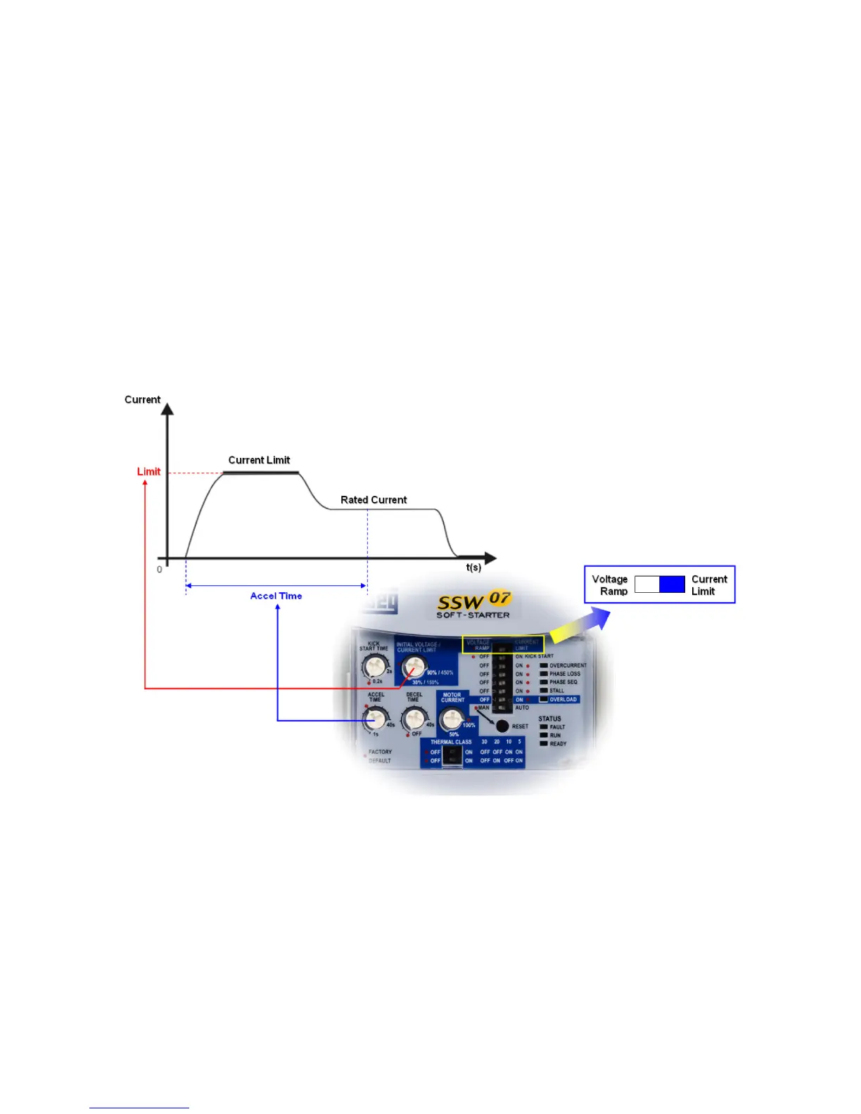
Trim-Pot and Dip Switch Settings (Figure 8):
1. Set the Voltage Ramp/Current Limit dip switch to the Current Limit position.
2. Set the Current Limit Trim-Pot using the following example.
Calculation example for limiting the current to 2.5 x I
N
of the motor:
– I
N
of the switch = 60A
– I
N
of the motor = 52A
– I
LIM
= 250% of the I
N
of the motor
– 2.5x 52A =130A
– 130A / I
N
of the switch = 130A / 60A = 2.17 x I
N
of the switch
– Current Limit = 217% of the I
N
of the switch = 2.5x I
N
of the motor
Figure 8 – Current Limiting
Notes: (1) The Current limitation must be set at a level that permits the motor to accelerate otherwise the motor will not
start. (2) If the full voltage is not reached at the end of the acceleration ramp time an E62 error will occur and the motor
will be disabled. For details on Fault Codes please refer to Chapter 6 in the SSW07 User’s Guide. (3) For details on
Current Limiting please refer to Chapter 5 in the SSW07 User’s Guide.
 Loading...