EasyManua.ls Logo

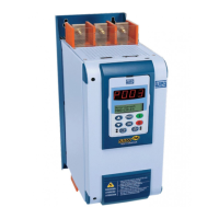
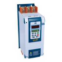
WEG SSW-06 User Manual

WEG SSW-06
195 pages
To Next Page IconTo Next Page
Page #1 background imageLoading...
Page #1 background image
Soft-Starter
Arrancador Suave
Soft-Starter
Sanftanlaufgerät
Устройство плавного пуска
SSW-06
Motors | Automation | Energy | Transmission & Distribution | Coatings
User's Manual
Manual del Usuario
Manual do Usuário
Bedienungsanleitung
Руководство пользователя

Table of Contents

Other manuals for WEG SSW-06

Questions and Answers:

WEG SSW-06 Specifications

General IconGeneral
TypeSoft Starter
Operating Frequency50/60 Hz
Protection DegreeIP20
Control MethodVoltage Ramp
ProtectionOverload, Phase Loss, Overvoltage, Undervoltage
Humidity95% RH non-condensing
Bypass ContactorOptional
CommunicationOptional Modbus RTU
Current Rating6A
Output Current6A
Operating Temperature-10°C to 50°C

Summary

Chapter 1 Safety Notices

1.1 Safety Notices in the Manual

Details safety instructions and guidelines within the manual for proper operation.

1.2 Safety Notices on the Product

Highlights safety symbols and warnings attached directly to the product for user awareness.

1.3 Preliminary Recommendations

Provides essential initial recommendations for installation, operation, and handling of the equipment.

Chapter 2 General Information

2.1 About this Manual

Outlines the manual's structure, purpose, and scope for user guidance.

2.2 Software Version

Explains the importance of the software version and its impact on functions and parameters.

2.3 About the Soft-Starter SSW-06

Describes the Soft-Starter SSW-06 as a high-performance drive for AC induction motors.

2.4 Soft-Starter SSW-06 Identification

Details how to identify the Soft-Starter SSW-06 model and its key information from the nameplate.

2.5 Receiving and Storage

Provides instructions for receiving, inspecting, and storing the Soft-Starter SSW-06 safely.

Chapter 3 Installation and Connection

3.1 Mechanical Installation

Covers essential aspects of mechanical installation, including environment and mounting.

3.1.1 Environment Conditions

Specifies environmental conditions like temperature, moisture, and altitude for proper installation.

3.1.2 Dimensions of the Soft-Starter SSW-06

Provides external dimensions and mounting hole details for physical installation planning.

3.1.3 Positioning / Fixing

Details recommendations for vertical installation and required free space for cooling airflow.

3.2 Electrical Installation

Guides the user through the electrical connections, wiring, and power supply setup.

3.2.1 Power Terminals

Illustrates power connection terminals for different models, detailing AC supply and motor connections.

3.2.2 Location of Power/Grounding, Control Connections and Fan Voltage Selection

Shows the location of power, grounding, control, and fan voltage selection terminals for various models.

3.2.3 Recommended Power/ Grounding Cables

Provides specifications for recommended power and grounding cables and busbars for standard and delta connections.

3.2.4 Connection of the Power Supply to the Soft-Starter

Details the procedures for connecting the AC input voltage and necessary safety precautions.

3.2.4.1 Short Circuit Capacity, Fuses, Circuit Breaker - UL

Presents UL standard requirements for short circuit capacity, fuses, and circuit breakers.

3.2.4.2 Input Circuit Breakers and Fuses - IEC

Specifies IEC standards for input circuit breakers and fuses, including ultra-fast fuse types.

3.2.5 Connection of the SSW-06 Soft-Starter to the motor

Explains how to connect the Soft-Starter to the motor using standard or inside delta configurations.

3.2.5.1 Standard Three-Wire Connection

Details the standard three-wire connection method for the motor and its implications on line current.

3.2.5.2 Inside Delta Motor Connection

Describes the inside delta motor connection, its current relationship, and wiring requirements.

3.2.6 Grounding Connections

Provides essential guidelines for proper grounding of the Soft-Starter and motor frame for safety.

3.2.7 Fan Connections

Explains how to connect and select the fan voltage for models equipped with cooling fans.

3.2.8 Signal and Control Connections

Details the connections for digital inputs, relay outputs, analog outputs, and motor thermistor on the electronic board.

3.2.9 RS-232, X2 Serial Communication Connection

Explains the serial communication interface for connecting to a PC or PLC via RS-232.

3.2.10 XC8 Serial Communication Board Connection

Describes the connection of the XC8 board for optional serial communication (RS-485 or USB).

3.2.11 XC6 Fieldbus Communication Board Connection

Explains the connection of the XC6 board for Profibus DP or DeviceNet communication.

3.3 RECOMMENDED SET-UPS

Presents various suggested set-ups for control and operation based on application needs.

Chapter 4 Keypad Operation

4.1 DESCRIPTION OF THE KEYPAD (HMI-SSW06)

Provides a detailed description of the keypad's layout, displays, LEDs, and keys.

4.2 USE OF THE KEYPAD

Explains how to use the keypad for operating and programming the Soft-Starter.

4.2.1 Keypad use for Soft-Starter SSW-06 Operation

Details how to perform start, stop, FWD/REV, JOG, and mode switching using the keypad.

4.2.2 Keypad Display - Signalling Indications

Describes the information displayed on the LED and LCD displays for status and parameter values.

4.2.3 Parameter viewing and programming

Guides users on how to view, select, and program parameters using the keypad interface.

Chapter 5 Start-Up

5.1 POWER-UP PREPARATION

Outlines the essential steps and checks required before powering up the Soft-Starter.

5.2 INITIAL POWER-UP (required parameter settings)

Details the start-up routine that guides the user through essential parameter programming for operation.

5.3 START-UP

Describes the start-up procedures for various control types via the keypad.

5.3.1 Start-up: Operation via Keypad Type of control: Voltage Ramp

Provides a step-by-step guide for starting the motor using the Voltage Ramp control via the keypad.

Chapter 6 Detailed Parameter Description

6.1 ACCESS AND READ ONLY PARAMETERS - P000 to P099

Explains parameters related to access, password settings, and read-only values for initial setup.

6.2 REGULATION PARAMETERS - P100 to P199

Details parameters for voltage ramp, current limit, pump control, and torque control settings.

6.3 CONFIGURATION PARAMETERS - P200 to P299

Covers parameters for password, language selection, type of control, and parameter loading/saving.

6.4 SERIAL COMMUNICATION PARAMETERS - P300 to P399

Details parameters for Modbus-RTU, Fieldbus protocols, and serial communication error actions.

6.5 MOTOR PARAMETERS - P400 to P499

Explains parameters for defining motor voltage, current, speed, power, and power factor.

6.6 SPECIAL FUNCTION PARAMETERS - P500 to P599

Covers parameters for braking methods, JOG function, kick start, and torque/speed profiles.

6.7 PROTECTION PARAMETERS - P600 to P699

Details parameters for undervoltage, overvoltage, current imbalance, thermal protection, and motor faults.

6.8 SELECTION BETWEEN FAULT AND ALARM - P700 to P790

Explains how to configure trips between fault and alarm states for various motor protections.

6.9 SOFTPLC PARAMETERS - P950 to P999

Covers parameters for enabling SoftPLC, digital inputs/outputs expansion, and user parameters.

Chapter 7 Programming Information and Suggestions

7.1 APPLICATIONS AND PROGRAMMING

Provides guidance on selecting and programming start control types based on load characteristics.

7.1.1 Starting by Voltage Ramp (P202=0)

Details the procedure for starting the motor using the Voltage Ramp method with parameter settings.

7.1.2 Starting by Current Limit (P202=1)

Explains how to start the motor using the Current Limit method, including parameter setup.

7.1.3 Starting by Current Ramp with High Initial Current (P202=4)

Guides on using Current Ramp with high initial current for loads requiring higher starting torque.

7.1.4 Starting by Current Ramp with Low Initial Current (P202=4)

Details using Current Ramp with low initial current for loads needing smoother starts.

7.1.5 Starting with Pump Control (P202=2)

Explains the Pump Control start method for hydraulic centrifugal pumps, including parameterization.

7.1.6 Starting with Torque Control (P202=3)

Describes the Torque Control method, its performance, and programming options for various loads.

7.1.6.1 Loads with Constant Torque (P202=3 and P120=1 point)

Details starting loads with constant torque using a single-point torque control profile.

7.1.6.2 Loads with Higher Initial Torque (P202=3 and P120=3 points)

Explains starting loads with higher initial torque using a three-point quadratic torque profile.

7.1.6.3 Loads with Constant Torque and S Speed Curve (P202=3 and P120=3 points)

Guides on starting loads with constant torque and S-curve speed using a three-point profile.

7.1.6.4 Loads with Quadratic Torque and S Speed Curve (P202=3 and P120=2 points)

Details starting loads with quadratic torque and S-curve speed using a two-point linear profile.

7.1.6.5 Loads with Quadratic Torque and Linear Speed Curve (P202=3 and P120=3 points)

Explains starting loads with quadratic torque and linear speed using a three-point profile.

7.1.6.6 Loads with Quadratic Torque and Higher Initial Torque (P202=3 and P120=3 points)

Guides on starting loads with quadratic torque and higher initial torque using a three-point profile.

7.1.6.7 Hydraulic Pump Load Type (P202=3)

Describes torque control for hydraulic pump loads, focusing on pressure ramp linearity.

7.2 PROTECTIONS AND PROGRAMMING

Covers motor protection settings, including thermal classes and over/under protections.

7.2.1 Thermal Classes

Explains how to set thermal classes for motor protection based on starting conditions and motor data.

7.2.1.1 Suggestions on How to Set Thermal Class

Provides suggestions for determining the minimum thermal class for cold motor starts.

7.2.1.2 Example on How to Set the Thermal Class

Illustrates setting thermal classes for both cold and hot motor starting conditions.

7.2.1.3 Time Reduction When Changing from Cold Starting to Hot Starting

Explains how to adjust activation times when transitioning from cold to hot motor starting.

7.2.1.4 Service Factor

Details how to use the service factor for finding thermal protection activation times.

7.2.2 Under- and Over- Protections

Covers setting undervoltage, overvoltage, underload, and overload protections for motor safety.

7.2.2.1 Undervoltage and Overvoltage protection

Explains how to configure undervoltage and overvoltage protection levels based on motor voltage tolerance.

7.2.2.2 Underload Protection

Details setting undercurrent, undertorque, or underpower protections for load detection.

7.2.2.3 Overload Protection

Explains how to configure overcurrent, overtorque, or overpower protections for motor safety.

Chapter 8 Diagnostics and Troubleshooting

8.1 FAULTS AND POSSIBLE CAUSES

Lists common faults, their descriptions, possible causes, and reset methods.

8.2 TROUBLESHOOTING

Provides a table of common problems, points to check, and corrective actions for troubleshooting.

8.3 TECHNICAL ASSISTANCE CONTACTING

Guides users on what information to provide when contacting WEG for technical assistance.

8.4 PREVENTIVE MAINTENANCE

Covers periodic inspections and general maintenance recommendations for the Soft-Starter.

8.4.1 Cleaning Instructions

Provides detailed instructions for cleaning the cooling system and electronic boards safely.

8.5 SPARE PART LIST

Lists available spare parts for the Soft-Starter SSW-06, including model and item numbers.

Chapter 9 Options and Accessories

9.1 REMOTE KEYPAD AND CABLES

Describes the remote keypad, mounting frame, and available connection cables.

9.2 RS-485 for the Soft-Starter SSW-06

Details the RS-485 interface for multi-drive control on a common bus with Modbus-RTU protocol.

9.2.1 RS-485 Communication Kit (KRS-485)

Provides information on the RS-485 communication kit, including part number and converter details.

9.2.2 Optional Module MIW-02

Describes the MIW-02 module for RS-232 to RS-485 conversion and its connection.

9.3 FIELDBUS COMMUNICATION KITS

Introduces communication boards required for Profibus DP or DeviceNet communication.

9.3.1 Fieldbus DeviceNet Communication Kit (KFB-DN)

Details the DeviceNet communication kit, its part number, and protocol features.

9.3.2 Fieldbus Profibus DP-V1 Communication Kit (KFB-PDPV1)

Describes the Profibus DP-V1 kit for linking controllers and industrial equipment.

9.3.3 Fieldbus DeviceNet Drive Profile Communication Kit (KFB-DD)

Explains the DeviceNet Drive Profile kit for fast, cyclic, and acyclic communication.

9.3.4 Fieldbus EtherNet/IP or Modbus/TCP Communication Kit (KFB-ENIP)

Details EtherNet/IP or Modbus/TCP kits suitable for industrial environments.

9.4 USB

Covers the serial communication interface conversion to USB.

9.4.1 USB Communication Kit (K-USB)

Provides details on the USB communication kit, including part number and internal connection.

9.5 INPUTS AND OUTPUTS EXPANSION BOARD

Describes the expansion board for increasing digital inputs and outputs, used with SoftPLC.

9.5.1 Digital Inputs and Outputs Expansion Kit (K-IOE)

Details the K-IOE expansion kit with digital I/Os, galvanically isolated, for SoftPLC.

9.5.2 PT100 Inputs Kit (K-PT100)

Describes the PT100 inputs kit for measuring motor temperature.

9.6 EXTERNAL CURRENT ACQUISITION

Explains the necessity of external current transformers for certain applications.

9.6.1 External Current Acquisition Kit (K-ECA)

Details the kit for external current acquisition, including components and part numbers.

Chapter 10 Technical Specifications

10.1 CURRENTS AND RATINGS ACCORDING TO UL508

Provides current and power ratings for standard connections according to UL508 standard.

10.2 CURRENTS AND RATINGS FOR IP55 IV POLE WEG MOTOR

Lists currents and power ratings for IP55 IV Pole WEG motors in standard connection.

10.3 POWER DATA

Details power-related specifications including supply voltage, frequency, and starting cycles.

10.4 ELECTRONICS/PROGRAMMING DATA

Covers specifications for control voltage, inputs, outputs, communication methods, and safety protections.

10.5 MECHANICAL DATA

Provides mechanical dimensions and mounting details for various Soft-Starter SSW-06 models.

Related product manuals