CHAPTER 3 - INSTALLATION AND CONNECTION
37
First install and partially tighten the mounting bolts, in agreement
withgures3.1and3.4andtable3.1,theninstalltheSoft-Starter
SSW-06 and tighten the mounting bolts.
Figure 3.5 - Procedures for keypad removal and front cover
opening for the control connections exposure
3.2 ELECTRICAL
INSTALLATION
DANGER!
Be sure that the AC input power is disconnected before making any
terminal connections.
DANGER!
The Soft-Starter SSW-06 cannot be used as an emergency stop
device.
ATTENTION!
The information below will be a guide to achieve a proper installation.
Also follow all applicable local standards for electrical installations.
Provide at least a 0.25m (10 in) space between sensitive equipment
and wiring from the Soft-Starter SSW-06, and the cables between
theSoft-StarterSSW-06andthemotor.Example:PLC,temperature
wiring, thermocouple cables, etc.
ATTENTION!
Ontherstpower-upofmodels45Ato365A,ifacontactorisnotused
to isolate the power input, and which will fall out upon under voltage,
thenthecontrolsupplymustbeconnectedrst andtheminimum
necessary parameters must be programmed after which the main
power may be connected.
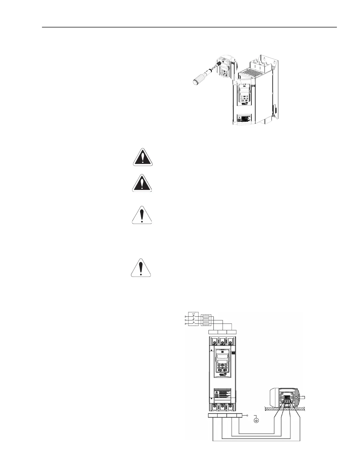
Figure 3.6 - Standard power/grounding connections
R/1L1
S/3L2 T/5L3
Circuit-breaker
Line
Fuses
R
S
T
U/2T1 W/6T3
PE
V/4T2
PE