CHAPTER 3 - INSTALLATION AND CONNECTION
62
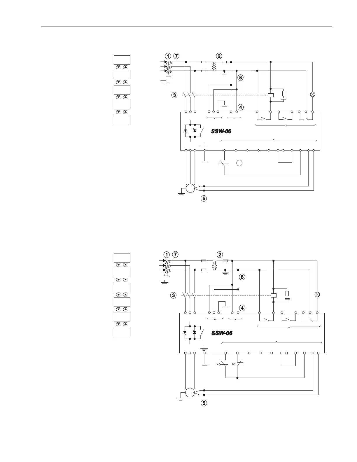
3.3.3 Recommended Set-up with Command via Two-wire Digital Inputs
Figure 3.24 - Recommended set-up with command via two-wire digital inputs
+ t
o
M
3~
PTC
R
S
T
PE
K1
R S T 1 2 PE
33 34
X1EX1A
18
19
RL1
RL2
20 21
22 23 24
RL3
X1C
X1B
Dl1
3
Dl2
4
Dl3
5
Dl4
6
Dl5
7
COM
8 9
0V
10
24V
11
PTC
B A
12 13
U V W
Fault
T1
K1
Start/
Stop
3.3.4 Recommended Set-up with Command via Three-wire Digital Inputs
Figure 3.25 - Recommended set-up with command via three-wire digital inputs
+ t
o
M
3~
PTC
R
S
T
PE
K1
R S T
1 2 PE 33 34
X1E
X1A
18 19
RL1
RL2
20
21
22 23
24
RL3
X1C
X1B
Dl1
3
Dl2
4
Dl3
5
Dl4
6
Dl5
7
COM
8 9
0V
10
24V
11
PTC
B A
12 13
U V W
Fault
T1
K1
Start
Stop
See notes in the item 3.3
See notes in the item 3.3
P230 =1
P220 =1
P263 =1
P279 =6
P277 =1
P277 =1
P264 =1
P230 =1
P220 =1
P279 =6
P263 =2

 Loading...